Hydraulic brake system for a vehicle

a brake system and hydraulic technology, applied in the direction of brake systems, braking components, transportation and packaging, etc., can solve the problems of throttling the flow of brake fluid, affecting the function of the brake system, and causing the accumulation of pressure,

Inactive Publication Date: 2000-05-09
ROBERT BOSCH GMBH
View PDF7 Cites 18 Cited by
  • Summary
  • Abstract
  • Description
  • Claims
  • Application Information

AI Technical Summary

Problems solved by technology

Problems arise if when the master cylinder is not actuated brake pressure is to be built up, an example being during drive slip control and dynamic driving control.
The pressureless brake fluid flows only slowly to the return feed pump, and the pressure buildup is therefore delayed.
However, the known vehicle brake system has the disadvantage that for the conventional brake actuation without anti-lock control, traction control or dynamic driving control, the precharge pump must be capable of having a flow through it in both directions, so as to assure the necessary flow of brake fluid from the storage container into the master cylinder and vice versa.
This makes it expensive.
A further factor is that because of the high pump rpm, cavitation and the formation of gas bubbles must be expected, which would cause damage to the centrifugal pump and lead to impairment in the function of the brake system.
Other types of pump as the precharge pump have the disadvantage of throttling the flow of brake fluid, that is, of hindering the flow of brake fluid from the storage container to the master cylinder and back.
Centrifugal and flyweight pumps are therefore poorly suited as precharge pumps.

Method used


Image

  • Hydraulic brake system for a vehicle
  • Hydraulic brake system for a vehicle
  • Hydraulic brake system for a vehicle

Examples


Embodiment Construction

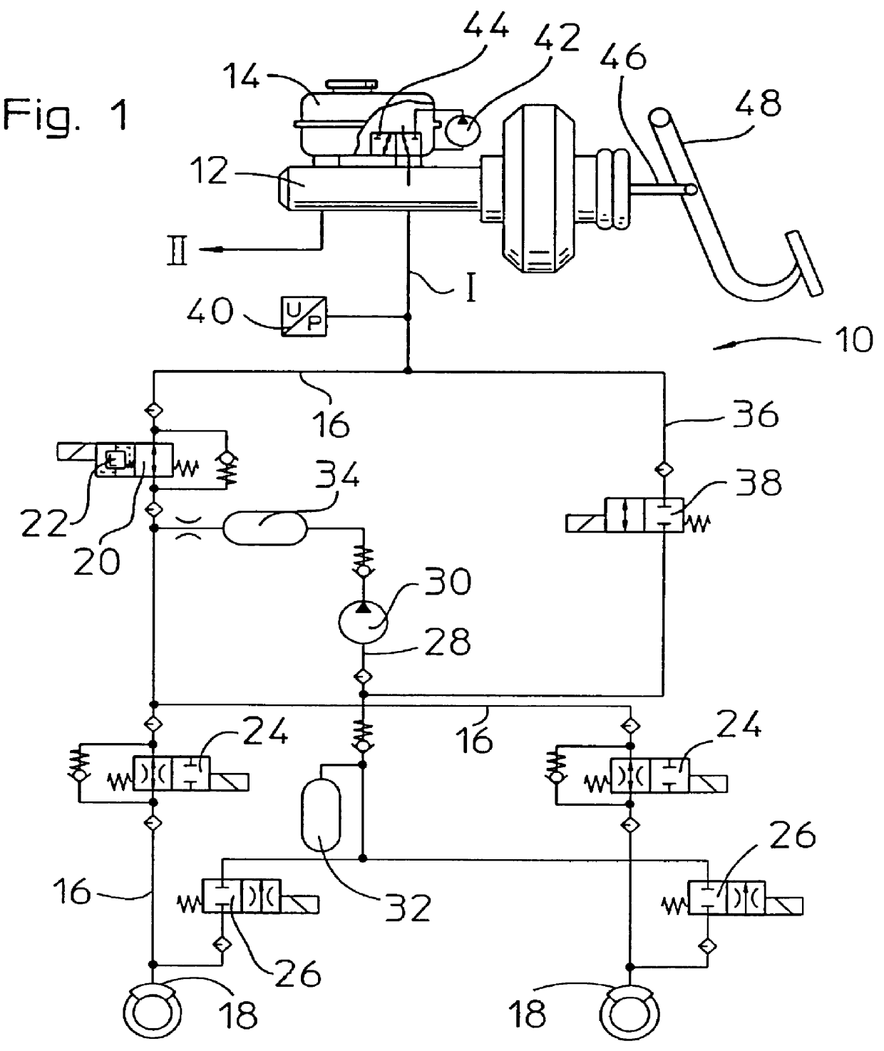
In FIG. 1, a brake circuit I of a dual-circuit vehicle brake system 10 according to the invention is shown. The brake circuit II, not shown, is structurally the same as the brake circuit I shown and functions in the same way.

The vehicle brake system 10 has a tandem master cylinder 12 with a storage container 14. A branching main brake line 16 leads to wheel brake cylinders 18 connected to this brake circuit I. A switchover valve 20, which is open in its basic position, with an integrated pressure limiting valve 22 is incorporated into the main brake line 16. Each wheel brake cylinder 18 is preceded by an inlet valve 24 which is open in its basic position.

Each wheel brake cylinder 18 also has an outlet valve 26, which is closed in its basic position, and from which a common return line 28 leads to the main brake line 16 and discharges between the switchover valve 20 and the inlet valves 24. Incorporated into the return line 28 is a return feed pump 30, which is preceded by a reservoi...


PUM


Abstract

PCT No. PCT/DE97/00921 Sec. 371 Date Jan. 8, 1998 Sec. 102(e) Date Jan. 8, 1998 PCT Filed May 7, 1997 PCT Pub. No. WO97/42067 PCT Pub. Date Nov. 13, 1997The invention relates to a vehicle hydraulic brake system having a traction control unit and a dynamic driving control unit. To enable building up pressure quickly with a return feed pump, even when the master cylinder is not actuated, a precharge pump, which is mounted on the storage container of the master cylinder and can be made to communicate with the master cylinder through a valve that is mounted in the storage container following the master cylinder. When the master cylinder is not actuated, pressure can be built up in the master cylinder and thus in the vehicle brake system using the precharge pump.

Description

PRIOR ARTThe invention relates to a hydraulic brake system for a vehicle having a traction control unit and a dynamic driving control unit.Known vehicle brake systems of this kind have a brake pressure modulating valve assembly with one inlet valve and one outlet valve for each wheel brake cylinder, and one return feed pump. The return feed pump, when the brake pressure in a wheel brake cylinder drops, pumps brake fluid released from the wheel brake cylinder back into the master cylinder, or pumps it into the wheel brake cylinder in order to raise the brake pressure.Problems arise if when the master cylinder is not actuated brake pressure is to be built up, an example being during drive slip control and dynamic driving control. The pressureless brake fluid flows only slowly to the return feed pump, and the pressure buildup is therefore delayed. This may still be acceptable for traction control, but for dynamic driving control a very much faster pressure buildup is necessary, to coun...

Claims


Application Information

Patent Timeline
Patent Type & Authority Patents(United States)
IPC IPC(8): B60T8/88B60T8/94B60T8/40B60T8/17B60T8/48B60T8/1755B60T8/24B60T8/175B60T8/34
CPCB60T8/175B60T8/1755B60T8/341B60T8/4881B60T8/94B60T8/4022B60T2270/306B60T2270/203
Inventor PUESCHEL, HELMUTSCHMIDT, GUENTHER
Owner ROBERT BOSCH GMBH
Why Eureka
Try Eureka