Method and system for predicting ship motion or the like to assist in helicopter landing

a technology for predicting the motion of the ship and helicopter, which is applied in the direction of navigation instruments, using reradiation, instruments, etc., can solve the problems of affecting the safe operation of the helicopter, the insurmountable task of landing the helicopter on the deck of the moving ship, and the inconvenient operation of the helicopter

Inactive Publication Date: 2000-05-16
LOCKHEED MARTIN CORP
View PDF11 Cites 73 Cited by
  • Summary
  • Abstract
  • Description
  • Claims
  • Application Information

AI Technical Summary

Problems solved by technology

Landing a helicopter on the deck of a moving ship is not an easy task even when the weather is good and the water is calm.
Deteriorating weather conditions and the associated increase in ship motion certainly make the helicopter landing on the deck of a moving ship almost an insurmountable task.
Hence, in a broad sense, the safe operational envelope of a helicopter is partially limited by the weather conditions which, at times, is so adverse that all helicopter operations must be suspended.
However, most of these procedures are performed under subjective human judgment along with some necessary conservative margins, which, more than often, results in larger ship heading changes, larger ship speed changes, or even premature suspensions of helicopter operations than theoretically necessary.
However, badly timed approaches may require the pilot to remain hovering in close proximity near the deck, waiting for a period of suitably benign ship motion.

Method used


Image

  • Method and system for predicting ship motion or the like to assist in helicopter landing
  • Method and system for predicting ship motion or the like to assist in helicopter landing
  • Method and system for predicting ship motion or the like to assist in helicopter landing

Examples


Embodiment Construction

The present invention is described with respect to an embodiment for providing a short-term prediction of future ship motion at sea. As described, the present invention is utilized for enhancing visual cueing information which can be remotely presented to a pilot during a helicopter-landing approach. Although a helicopter is utilized to illustrate the present invention, those skilled in the art will appreciate that the present invention may also be applicable to fixed-wing aircraft. In addition, the present invention is also applicable for providing a feed-forward control input to an active stabilization system utilized by any type of vessel, ship, or floating structure, and the scope of the present invention extends to such embodiments.

I. OVERVIEW

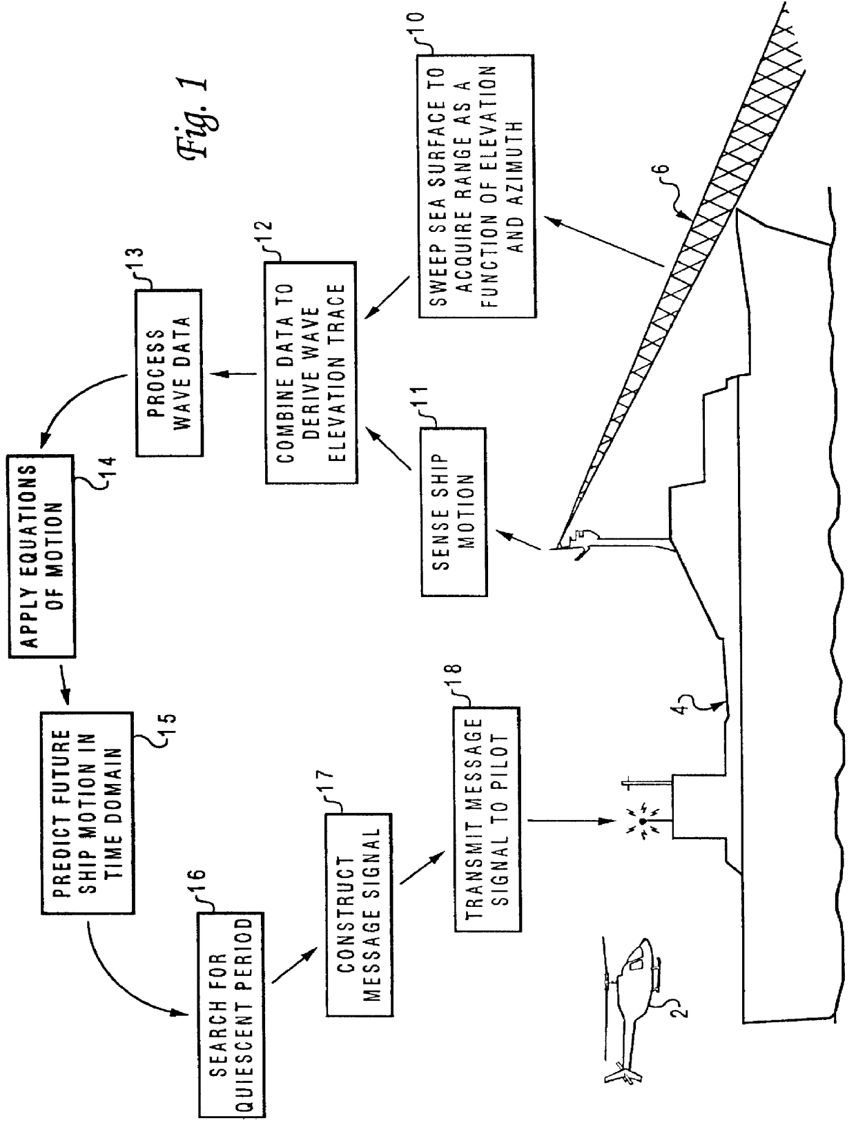
Referring now to the drawings and in particular to FIG. 1, there is depicted a functional block diagram of a method and system for predicting short-term ship motion to assist in landing a helicopter 2 on a ship 4, according to the preferre...


PUM


Abstract

A method for a short-term prediction of future ship motion in open water to furnish visual cueing information that can be remotely presented to a pilot during an aircraft landing is described. Two sets of samples of the sea surface geometry along a radial azimuth line from a ship as a function of elevation of a sensor are first acquired. These are compensated to remove the components due to the ship's motion. Two wave traces are then separately derived in Cartesian format from the two sets of acquired samples. These wave traces are subjected to a Fast Fourier Transform to detect the amplitudes and phases of the individual wavelength components. The direction of the wavelength components is determined using a measure of their phase change in the scan direction during the time interval between the two scans together with their measured wavelength. The amplitude, direction and phase of each component is utilized together with the known motion characteristics of the moving ship in order to derive a short-term prediction of future ship motion in the time domain. A quiescent period of the ship motion is located by comparing the short-term prediction with the pre-defined operating limit criteria. Finally, a message signal is transmitted to the pilot of the aircraft indicating Time-to-Land and the duration of the quiescent period.

Description

1. Technical FieldThe present invention relates to a method and system for motion prediction in general and, in particular to a method and system for predicting the motion of a ship. Still more particularly, the present invention relates to a method and system for a short-term prediction of future ship motion to provide visual cueing information to assist a pilot during a helicopter landing.2. Description of the Prior ArtLanding a helicopter on the deck of a moving ship is not an easy task even when the weather is good and the water is calm. Deteriorating weather conditions and the associated increase in ship motion certainly make the helicopter landing on the deck of a moving ship almost an insurmountable task. Hence, in a broad sense, the safe operational envelope of a helicopter is partially limited by the weather conditions which, at times, is so adverse that all helicopter operations must be suspended.Needlessly to say, in a Search and Rescue situation, many lives can be saved ...

Claims


Application Information

Patent Timeline
Patent Type & Authority Patents(United States)
IPC IPC(8): G01S13/00G01S13/91G01S13/95G01S7/02G01S7/41G08G3/00G01S7/00
CPCG01S7/411G08G3/00G01S13/956G01S13/913G01S7/003G05D1/0684Y02A90/10B63B79/15
Inventor FLEISCHMANN, DOMINIQUE S.
Owner LOCKHEED MARTIN CORP
Why Eureka
Try Eureka