Laser along-body tracker (SABOT III)

a technology of laser beam and tracking system, which is applied in the direction of optical radiation measurement, distance measurement, and instruments for comonautical navigation, etc., can solve the problems of loss of the track of the targeted moving object, ineffective elimination of interference, and limitations of imaging system when used in combination with high-power laser beam weaponry

Inactive Publication Date: 2000-05-23
NORTHROP GRUMAN CORP
View PDF11 Cites 21 Cited by
  • Summary
  • Abstract
  • Description
  • Claims
  • Application Information

AI Technical Summary

Problems solved by technology

While such imaging systems are effective in tracking targeted moving objects, such imaging systems are known to have limitations when used in combination with high power laser beam weaponry.
For example, in such systems, the high power laser beam is known to interfere with the imaging system potentially causing loss of the track of the targeted moving object.
Although various systems are known compensate for such an interference problem, such systems do not effectively eliminate the interference.
Unfortunately, laser based tracking systems are subject to what is known as thermal blooming.
The problem of thermal blooming also reduces the effectiveness of high power laser weaponry.

Method used


Image

  • Laser along-body tracker (SABOT III)
  • Laser along-body tracker (SABOT III)
  • Laser along-body tracker (SABOT III)

Examples


Embodiment Construction

An imaging type tracking system in illustrated in FIGS. 11-18 and generally identified with the reference numeral 200. A block diagram of the imaging type tracking system 200 in accordance with the present invention is illustrated in FIG. 11. As shown, the imaging type tracking system 200 includes an image tracker 202, a signal processor 204 and a fast steering mirror 206 forming a closed loop.

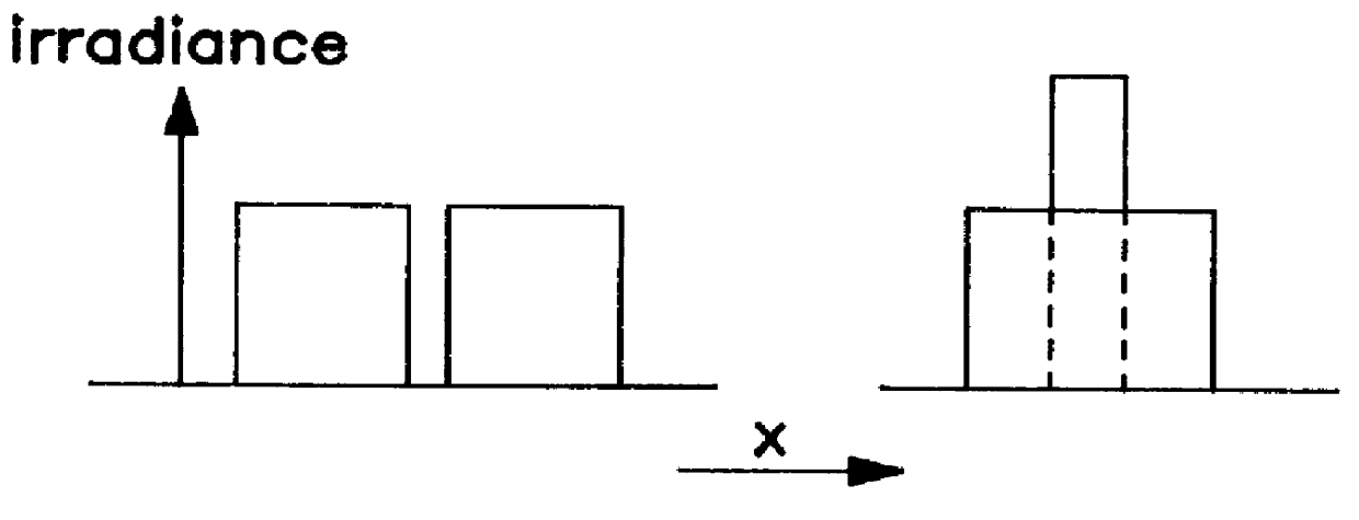
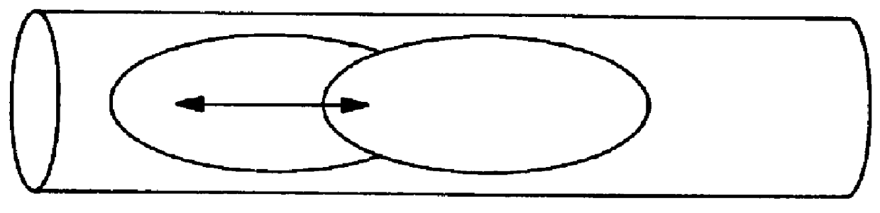
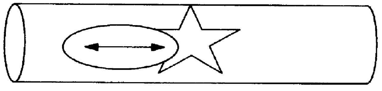
The block diagram for the imaging type tracking system 200 illustrated in FIG. 11 is similar to the block diagram for the non-imaging tracking system illustrated in FIG. 4. However, the imaging type tracking system 200 in accordance with the present invention eliminates the need for the one dimensional scanning receiver system 36 illustrated in FIG. 5. Rather the imaging type tracking system 200 develops an error signal in order to lock a slave beam from a slave laser 210 to a reference beam from a reference laser 208 at a point 212 on a moving target 214 such as a missile. As will be discusse...


PUM


Abstract

A laser-based tracking system for tracking the position of a targeted moving object. The tracking system includes two lasers: a reference laser and a slave laser. Each laser is a weapon, and when locked on a target, single laser effectiveness may be doubled without a thermal blooming performance loss associated with a single laser operating at twice the power. The slave laser beam is dithered relative to the reference laser beam in a direction along the longitudinal axis of the target. The system includes an optical receiver for repetitively scanning the irradiance profile reflected by the target. Since the slave laser beam is dithered relative to the reference laser beam, both laser beams will jitter and drift together providing a gain factor of two in average irradiance on the moving target.

Description

1. Field of the InventionThe present invention relates generally to systems for tracking a moving object and, more particularly, to a conventional imaging laser-based system for tracking a moving object that employs two lasers; a reference and slave laser. Each laser is a weapon, and when locked together on a target, single laser effectiveness may be doubled without a thermal blooming performance loss associated with a single laser operating at twice the power. The slave laser is dithered relative to the reference laser in a direction along a longitudinal axis of the target. The system includes an optical signal processing system which sums the pixel irradiance values from the target to create an error signal to lock the slave laser to the reference laser.2. Description of the Prior ArtVarious types of systems are known for tracking moving objects, such as rockets and missiles. Such systems can be categorized as either imaging or non-imaging. Imaging types systems normally utilize a...

Claims


Application Information

Patent Timeline
Patent Type & Authority Patents(United States)
IPC IPC(8): F41G3/04F41H13/00F41G3/00G01S17/66G01S17/00G01S17/02G01S17/86
CPCF41G3/04G01S17/66G01S17/023F41H13/005G01S17/86
Inventor LIVINGSTON, PETER M.
Owner NORTHROP GRUMAN CORP
Why Eureka
Try Eureka