Minimizing high power laser thermal blooming in the atmosphere

a high-power laser and atmosphere technology, applied in the direction of laser details, directed energy weapons, electrical equipment, etc., can solve the problems of thermal blooming, single pulse is generally not enough for most missions, and the beam is directly in the path so as to minimize thermal blooming, increase the fluence of the laser beam, and increase the effect of the interaction with the targ

Inactive Publication Date: 2006-03-07
SMITH DAVID C
View PDF4 Cites 0 Cited by
  • Summary
  • Abstract
  • Description
  • Claims
  • Application Information

AI Technical Summary

Benefits of technology

[0007]Objects of the invention include minimizing thermal blooming in the path of a high power laser beam in the atmosphere; increasing the fluence of a laser beam at a target, thereby to provide more

Problems solved by technology

One of the major problems encountered with high powered laser beams in the atmosphere is an effect known as “thermal blooming”.
The heating and therefore the distortion of the beam is directly in the path of the laser beam and can be quite severe.
Therefore, a

Method used


Image

  • Minimizing high power laser thermal blooming in the atmosphere
  • Minimizing high power laser thermal blooming in the atmosphere
  • Minimizing high power laser thermal blooming in the atmosphere

Examples


Embodiment Construction

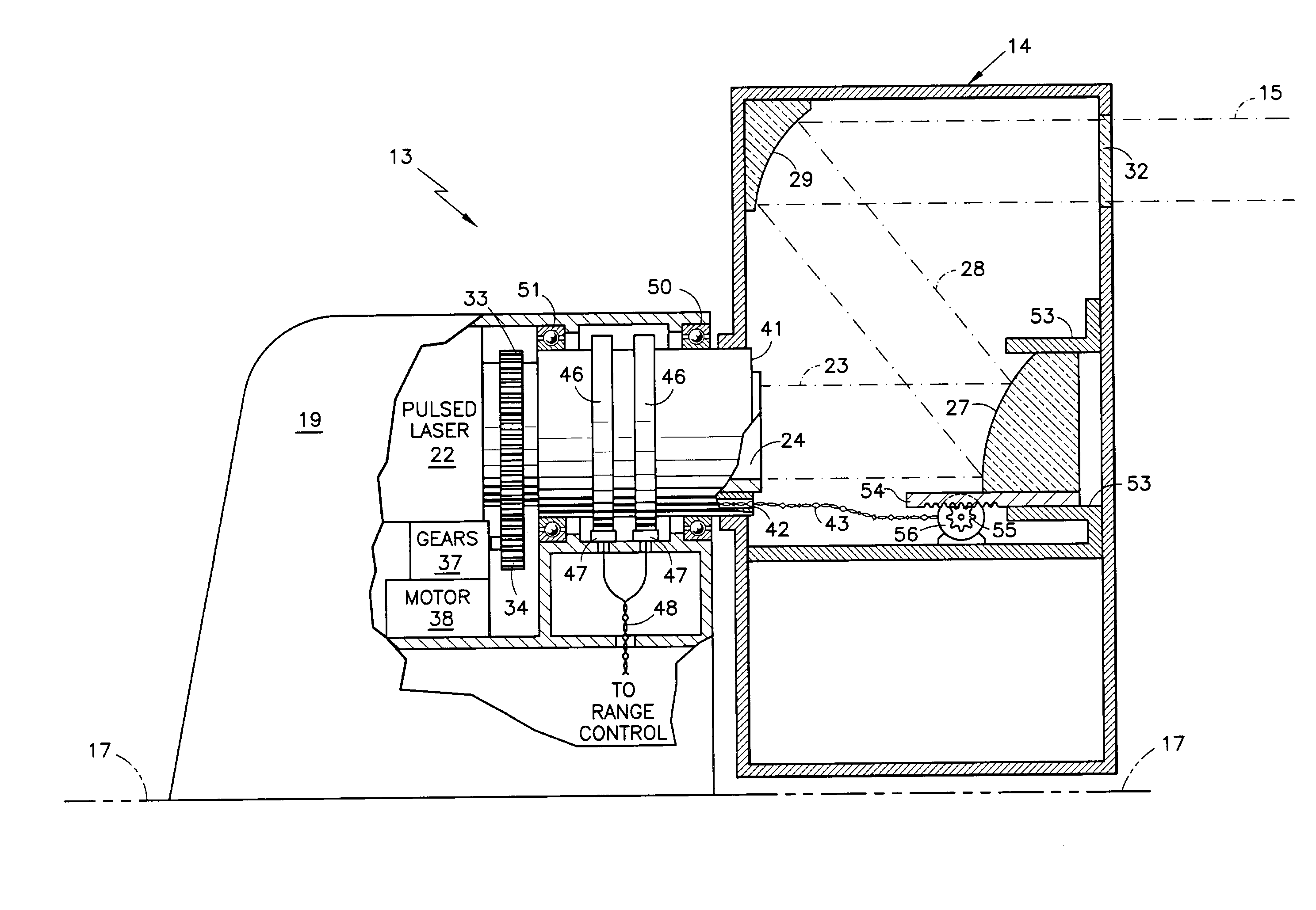
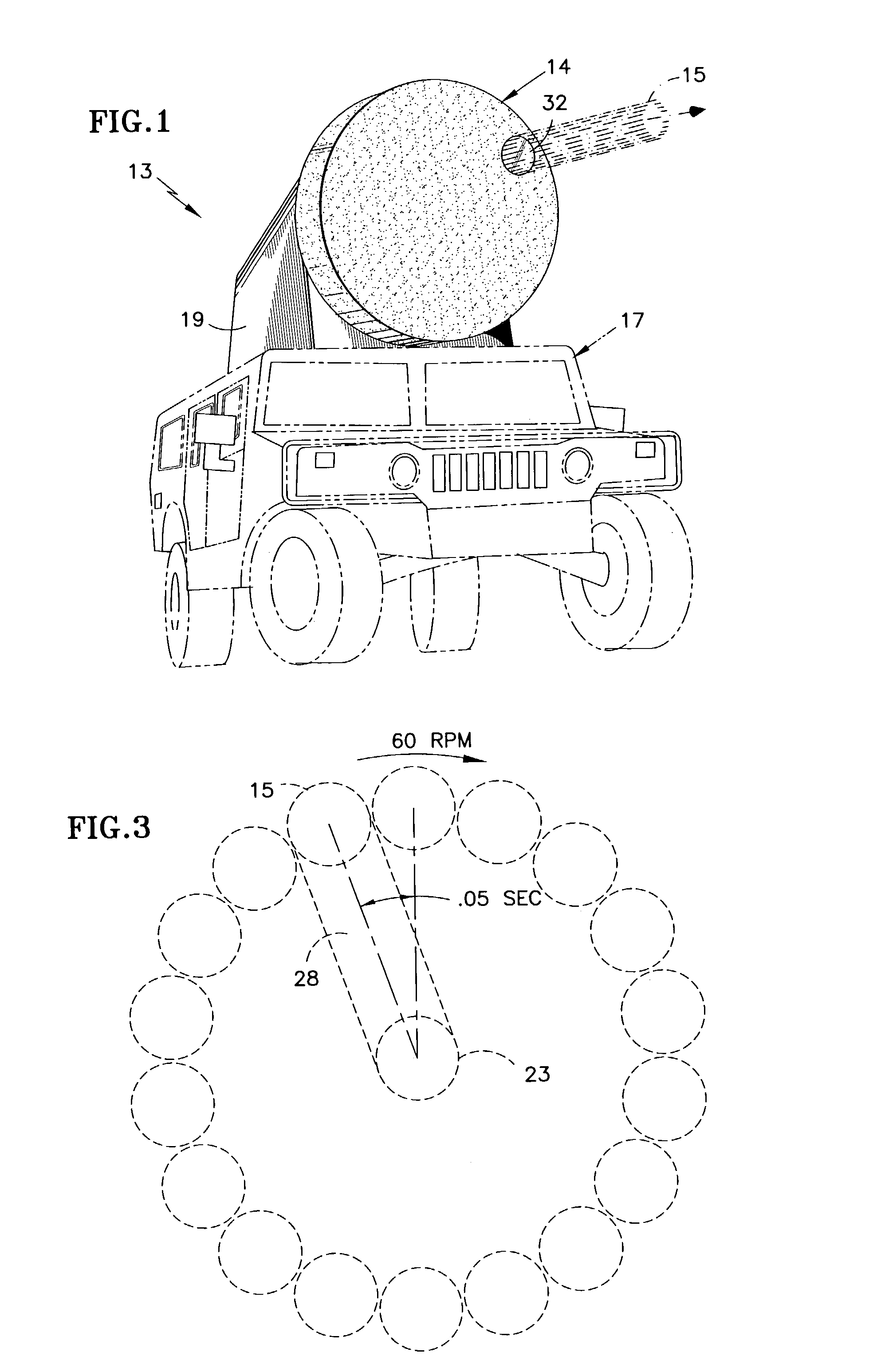
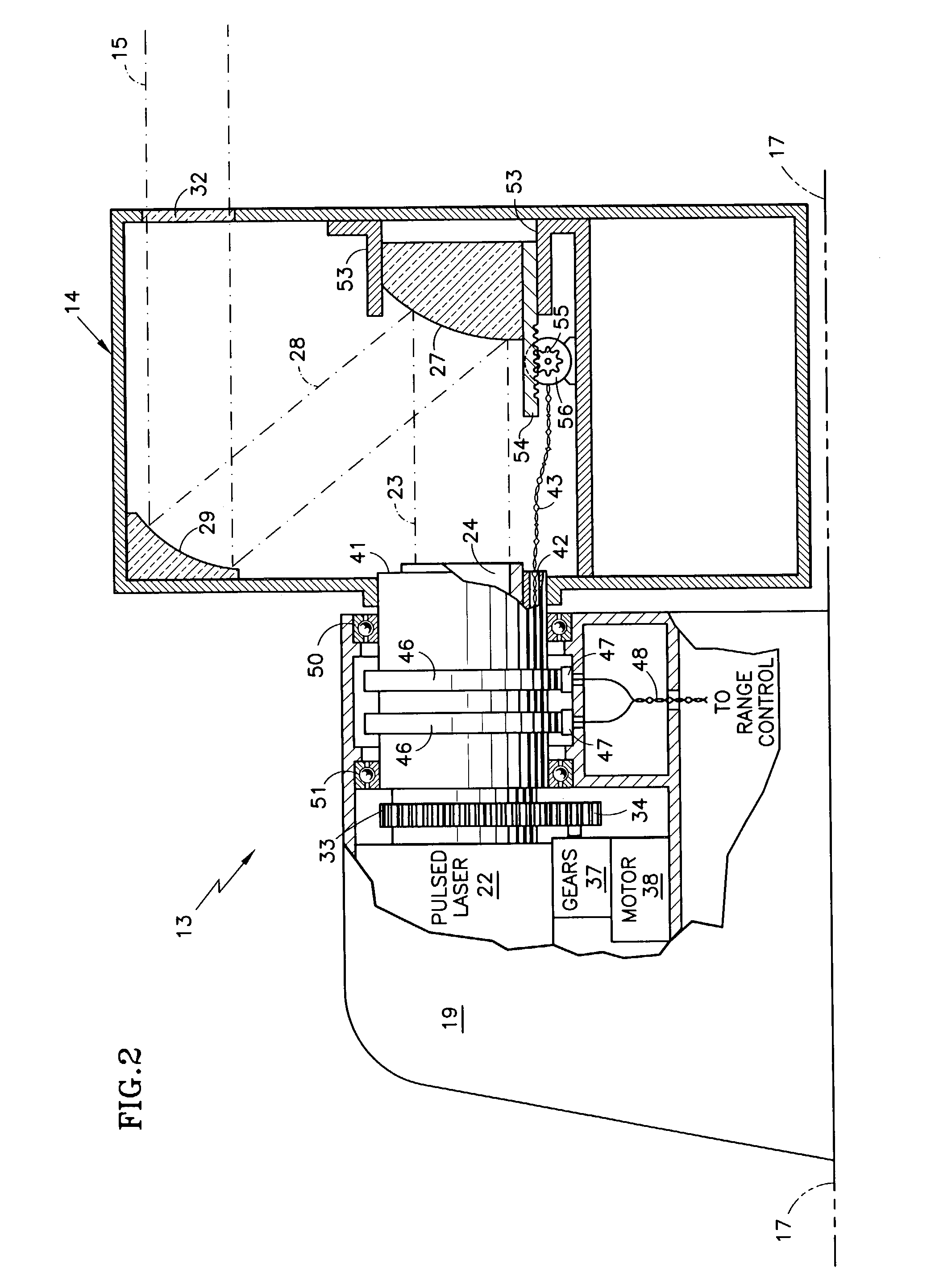
[0015]Referring to FIG. 1, a laser system 13 having a rotary optical antenna 14 that controls spacing of successive radar pulses 15, is disposed on a military vehicle 17. The laser system 13 includes a housing 19 within which the laser, the apparatus for rotating the optical antenna 14, and range control apparatus are all housed.

[0016]In FIG. 2, a pulsed laser 22 provides a laser beam 23 through a circular waveguide 24. The beam impinges on a convex mirror 27 to provide a reflected beam 28 to a concave mirror 29. This in turn provides the output beam 15 through a nearly 100% transmissive window 32. The optical antenna 14 along with the circular waveguide 24 are rotated such as by means of a gear 33 driven by a pinion 34 which in turn is rotated through suitable gear reduction 37 by a motor 38. A cylinder 41, having a bore 42 therein to permit the passage of wires 43, is disposed about the circular waveguide 24. On the cylinder 41 are slip rings 46 which coact with brushes 47 to prov...


PUM


Abstract

The output of a high power pulsed or CW laser (22), which may be mounted on a vehicle (17) is reflected from a convex mirror (27) to a concave mirror (29) that is displaced radially outward on a rotating structure (14) from the convex mirror by at least two beam diameters so that each pulse emanates from a position around a circle which is displaced from adjacent pulses by at least the diameter of the beam, thereby to minimize thermal blooming, or the position of a CW output laser beam is slewed. Directing the beams so that all of them will converge at a target area which is a given range from the apparatus is achieved by moving the convex mirror axially in response to range control signals provided through brushes (47) and slip rings (46). The rotating structure (14) including the laser waveguide (24) is journaled by bearings (50, 51) for rotation by a gear in response to a pinion (34) and gear reduction (37) driven by a motor (38).

Description

TECHNICAL FIELD[0001]This invention relates to the minimizing of thermal blooming which results from a high power laser beam heating the atmosphere, such as in a laser weapon.BACKGROUND ART[0002]The use of high powered lasers as weapons is known. One of the major problems encountered with high powered laser beams in the atmosphere is an effect known as “thermal blooming”. The effect is a result of the heating of the atmospheric elements along the path of the beam by the absorption of a small amount of the laser energy by the elements in the atmosphere. The heating causes differential phase changes at incremental positions along the beam path, which in turn causes the laser energy to become more widely dispersed. The heating and therefore the distortion of the beam is directly in the path of the laser beam and can be quite severe. The result is that at a target, the power per unit area (fluence) is smaller than that required to do the requisite amount of damage.[0003]Continuous wave ...

Claims


Application Information

Patent Timeline
IPC IPC(8): H01S3/10H01S3/00
CPCF41H13/005
Inventor SMITH, DAVID C.
Owner SMITH DAVID C
Why Eureka
Try Eureka