Artificial muscle actuator assembly

a technology of actuators and muscles, applied in the direction of flexible wall reciprocating engines, reciprocating piston engines, positive displacement engines, etc., can solve the problems of industrial devices, rotary actuators, and unsuitable for biorobotics use, and achieve the effect of substantial flexibility

Inactive Publication Date: 2000-05-30
ERICKSON JOEL R
View PDF32 Cites 95 Cited by
  • Summary
  • Abstract
  • Description
  • Claims
  • Application Information

AI Technical Summary

Benefits of technology

Accordingly, it is an object of the present invention to provide an

Problems solved by technology

These industrial devices, however, are often not suitable for use in biorobotics due to their non-natural compliance of robotic movement, as compared to natural human movement.
Rotary-type actuators, which transmits energy by applying a torque to a shaft rotating about a longitudinal axis thereof, are typically difficult to incorporate as artificial muscle replacements.
These conversion mechanisms, such as linkages, cams, gears, pulleys, etc., become very cumbersome to arrange when attempting to apply these actuators to prosthetic devices which often require that many actuators fit into a small deformable volume while maintaining the high volumetric functional efficiencies of biological musculo-skeletal systems.
One substantial problem associated with hydraulic cylinders is that they must be substantially rigid since a fluid tight seal must be formed between the cylinder walls and the opposed surface of the inner piston.
These small clearances, however, are difficult to maintain for flexible materials.
Therefore, conventional hydraulic cylinders are usually substantially rigid s

Method used


Image

  • Artificial muscle actuator assembly
  • Artificial muscle actuator assembly
  • Artificial muscle actuator assembly

Examples


Embodiment Construction

While the present invention will be described with reference to a few specific embodiments, the description is illustrative of the invention and is not to be construed as limiting the invention. Various modifications to the present invention can be made to the preferred embodiments by those skilled in the art without departing from the true spirit and scope of the invention as defined by the appended claims. It will be noted here that for a better understanding, like components are designated by like reference numerals throughout the various figures.

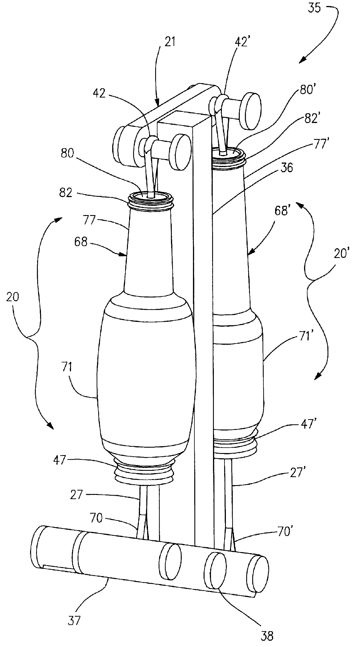
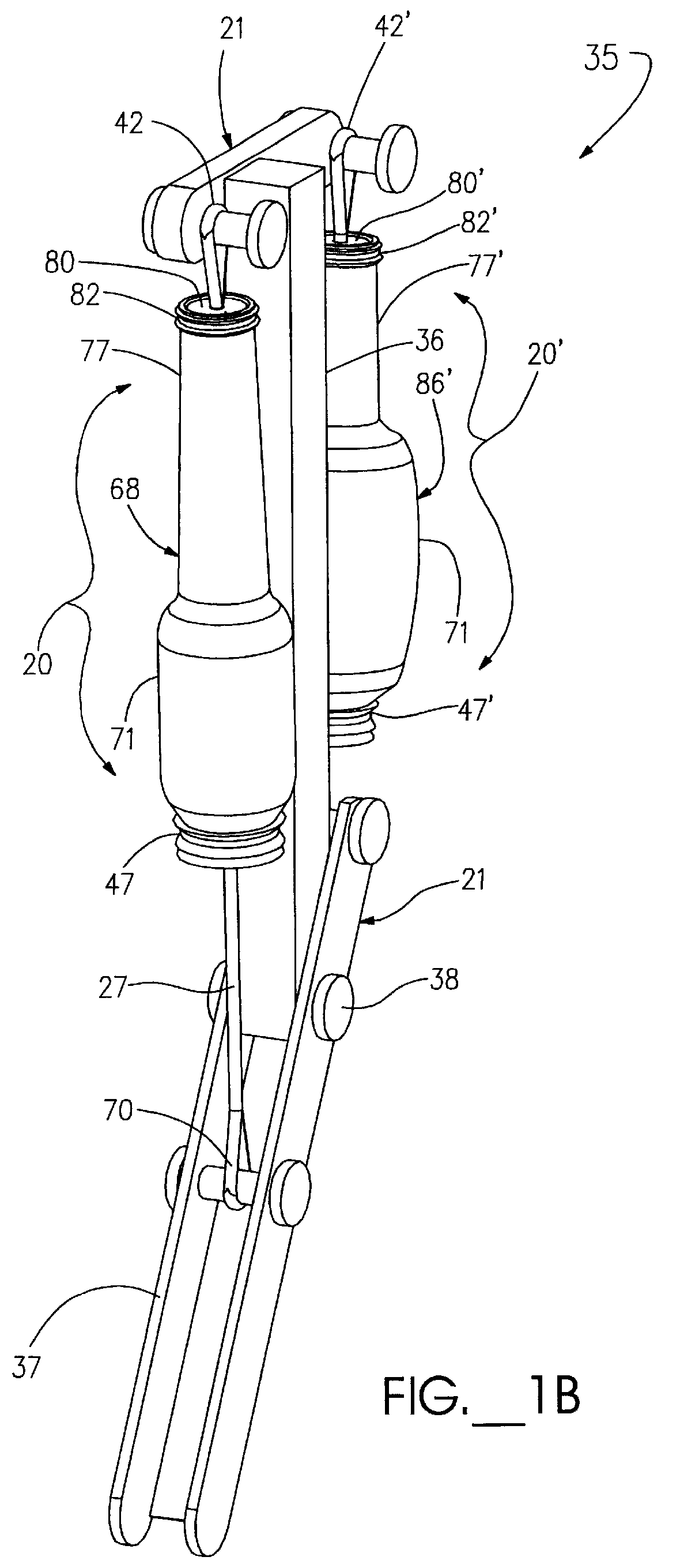
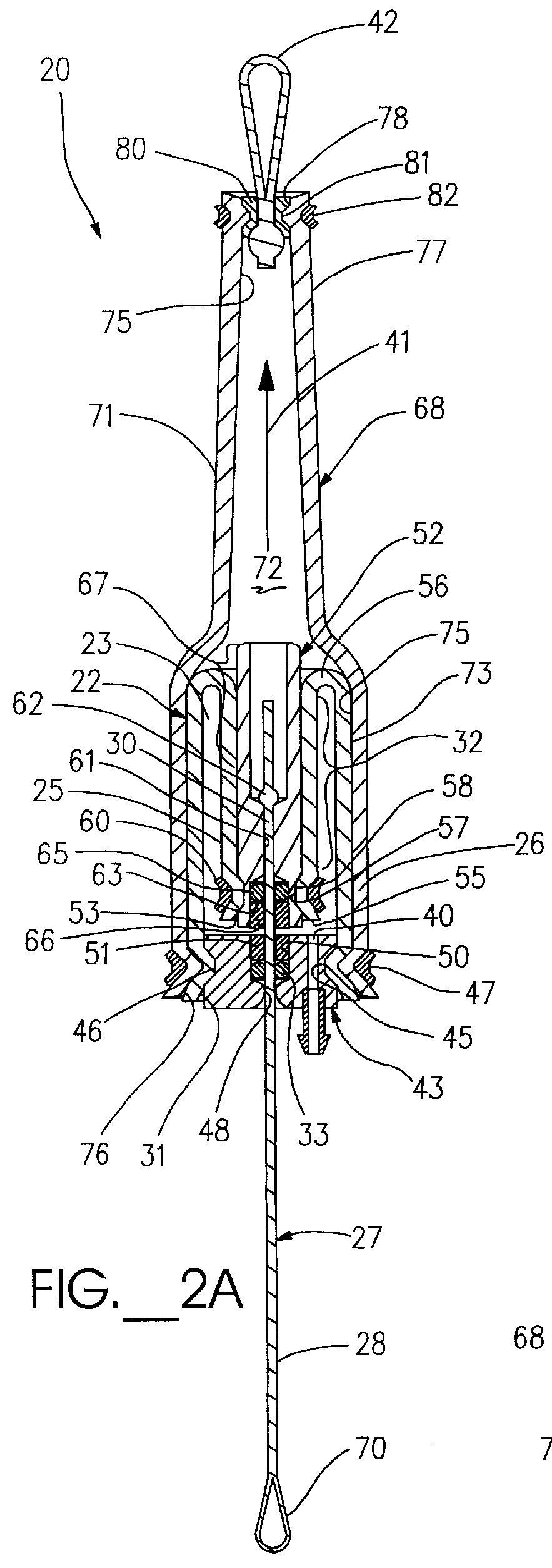
Attention is now directed to FIGS. 1 and 2 where a flexible actuator assembly, generally designated 20, is provided preferably to facilitate movement of a robotic device 21 (FIG. 1). The flexible actuator assembly 20 includes a flexible bladder device, generally designated 22, providing an expandable chamber 23 between a proximal portion 25 and an opposite distal portion 26 thereof. The bladder device 22 is adapted to substantially direc...


PUM


Abstract

A flexible actuator assembly (20) including a flexible bladder device (22) having an expandable sealed chamber (23) adapted to substantially directionally displace between a deflated condition and an inflated condition, displacing a proximal portion (25) of the bladder device (22) away from a distal portion (26) thereof. An elongated tendon member (27) includes a distal portion (28) oriented outside the chamber (23), while an anchor portion (30) extends into the chamber (23) through a distal opening (31) in the bladder device (22). The tendon anchor portion (30) is further coupled proximate to the bladder proximal portion (25) in a manner adapted to: selectively invert displaceable portions (32) of the bladder device (22) when urged toward the deflated condition to position the anchor portion (30) and the bladder proximal portion (25) relatively closer to the bladder distal portion (26); and selectively evert the inverted displaceable portions (32) of the bladder device (22) when displaced toward the inflated condition which positions the anchor portion (30) and the bladder proximal portion (25) relatively farther away from the bladder distal portion (26) for selective movement of the tendon distal portion (28) between an extended condition and a retracted condition, respectively.

Description

The present invention relates, generally, to actuator assemblies and, more particularly, relates to flexible artificial muscle actuator assemblies.In the recent past, industrial robotic devices have played an increasing and more pivotal role in the manufacture of commercial products. These robotic actuator devices can typically be classified into either linear-type actuators or rotary-type actuators, both of which are generally constructed as rigid mechanical structures generating substantial forces and / or torque. These industrial devices, however, are often not suitable for use in biorobotics due to their non-natural compliance of robotic movement, as compared to natural human movement.Biorobotic actuator devices which have been found suitable for use with, or as a replacement of, biological musculo-skeletal anatomies often include rigid skeletal structures moved by flexible artificial muscle actuators constructed to mimic the form and function of the biological components of real ...

Claims


Application Information

Patent Timeline
IPC IPC(8): F15B15/00F15B15/10
CPCF15B15/103
Inventor ERICKSON, JOEL R.
Owner ERICKSON JOEL R
Why Eureka
Try Eureka