Temperature/humidity controller for use in an air conditioner and a recording medium storing temperature/humidity control programs used therefor

a temperature/humidity controller and recording medium technology, applied in the direction of domestic cooling devices, heating types, instruments, etc., can solve the problems of increasing energy loss and running costs, difficult to actually determine, and complicated control, etc., to achieve stab control, save energy, and good response

Inactive Publication Date: 2000-06-27
TRINITY IND CORP
View PDF12 Cites 43 Cited by
  • Summary
  • Abstract
  • Description
  • Claims
  • Application Information

AI Technical Summary

Benefits of technology

In this case, since the aimed exit temperature for each of them is set to an optimum value as the process temperature for controlling the outside air to predetermined temperature/humidity based on the controlling line and since the te...

Problems solved by technology

Thus, troublesome and complicated control has been necessary.
As described above, since air conditioning in the prior art requires control process of heating (main heater H).fwdarw.cooling (adiabatic humidifier W).fwdarw.heating (auxiliary heater RH), or control process of humidification (adiabatic humidifier W).fwdarw.dehumidification (cooler C).fwdarw.humidification (isothermal humidifier DS), this results in problems of increasing energy loss and running cost due to the wasteful control process.
However, it is not easy to actually determine the exit temperature of each of the temperature/humidity adjusting d...

Method used


Image

  • Temperature/humidity controller for use in an air conditioner and a recording medium storing temperature/humidity control programs used therefor
  • Temperature/humidity controller for use in an air conditioner and a recording medium storing temperature/humidity control programs used therefor
  • Temperature/humidity controller for use in an air conditioner and a recording medium storing temperature/humidity control programs used therefor

Examples


first embodiment

Operation of the First Embodiment

The constitution of the first embodiment of the present invention has been described above and the operation of this embodiment will be explained next.

At first, when the upper limit state point Ps for the atmospheric temperature at 28.degree. C. and relative humidity at 75% as a coating booth atmosphere in the summer season, and the lower limit state point Pw for the atmospheric temperature at 20.degree. C. and the relative humidity at 75% as the coating booth atmosphere in the winter season are set on the psychrometric chart recorded in the psychrometric chart table 13, the aimed temperature / humidity line setter 14 sets an aimed temperature / humidity line Lo formed by connecting the upper limit state point Ps and the lower limit state point Pw.

Then, when the aimed temperature / humidity line Lo is set, the control area setter 15 sets the following four area:

a low temperature control area A.sub.1 for conducting control mainly in the winter season, a low...

modified first embodiment

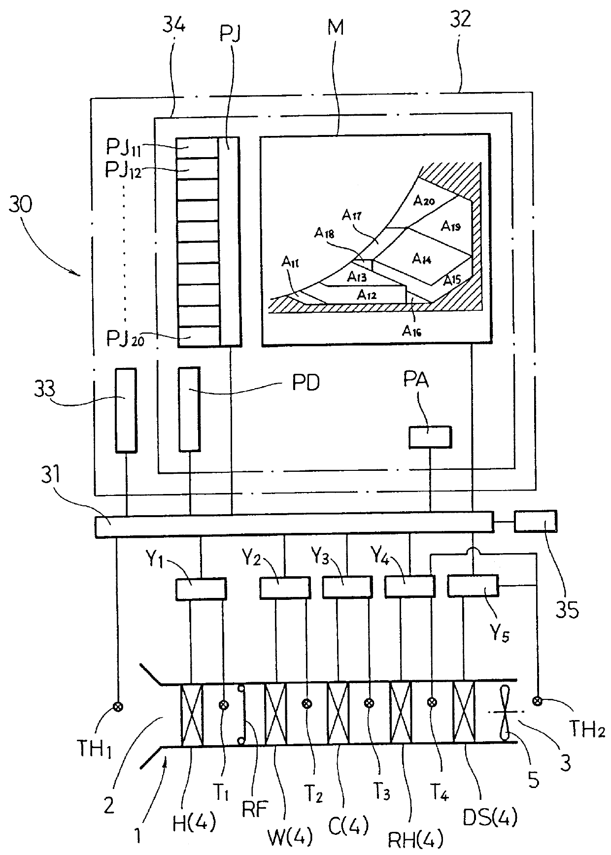
Explanations have been made to the first embodiment in which the area in the psychrometric chart is previously divided into a plurality of control areas A.sub.1 -A.sub.4, and each of the heating / humidifying devices 4, 4, - - - used in each of the areas is previously set. However, the present invention is not restricted to such an embodiment. For example, each of the temperature / humidity adjusting devices 4, 4, - - - to be used may be selected and the aimed exit temperature for each of the capacity controllers Y.sub.1 -Y.sub.5 may be set by drawing each of the controlling lines J.sub.1 -J.sub.5 from each of the outside air state points G.sub.1 -G.sub.5 to an optional state point on the aimed temperature / humidity line Lo without previously dividing the area into the control areas A.sub.1 to A.sub.4.

Further, while the first embodiment has been explained in that the psychrometric chart is divided into the four control areas A.sub.1 -A.sub.4, the area may be divided more finely depending...

second embodiment

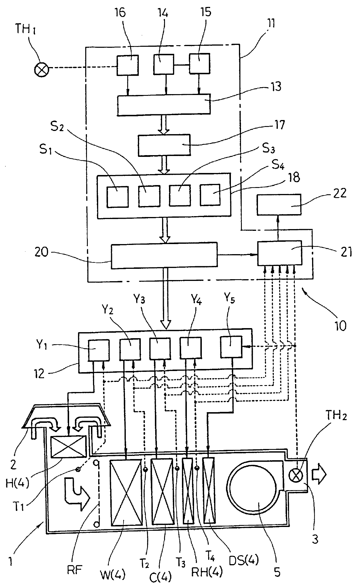
A temperature / humidity controller 30 for an air conditioner shown in FIG. 3 is adapted such that a main controller 32 is operated in accordance with computer programs, in which portions or components in common with those in the first embodiment carry the same reference numerals for which detailed explanations are to be omitted.

In the temperature / humidity controller 30, a temperature / humidity sensor TH.sub.1 is connected by way of an I / O port 31 to the input of a main controller 32, and capacity controllers Y.sub.1 -Y.sub.5 for controlling the capacity of temperature / humidity adjusting devices 4, 4, - - - are connected to the output of the main controller 32.

The capacity controllers Y.sub.1 -Y.sub.5 are connected, at the input thereof, with temperature sensors T.sub.1 -T.sub.4 and a temperature / humidity sensor TH.sub.2 disposed at the exit for the temperature / humidity adjusting devices 4, 4, - - - , respectively. Further, the temperature / humidity adjusting devices 4, 4, - - - are con...


PUM


Abstract

In a main controller for use in an air conditioner for controlling temperature/humidity of an intaken outside air, a controlling line setter (18) sets each of control lines (J1-J5) on a psychrometric chart table (13), in which an aimed temperature/humidity line (Lo) is formed by connecting an upper limit state point (Ps) and a lower limit state point (Pw) of condition air from each of the outside air state points (G1-G5) to the aimed temperature/humidity line (Lo). The controlling line (J1-J5) is formed by connecting necessary lines selected from a main heating line (HL) showing the heating operation of a main heater (H), an adiabatic humidifying line (WL) showing the humidifying operation of an adiabatic humidifying device (W), a cooling line (CL) showing the cooling operation of a cooler (C) and an auxiliary heating line (RHL) showing the heating operation of the auxiliary heater (RH), and the end point temperature for each of the lines is set as the aimed exit temperature for each of the temperature/humidity adjusters (4, 4) and each of the temperature/humidity adjusters (4-4) is individually put to feedback control. Temperature/humidity control can be conducted accurately and at a good response, and energy can be saved and the running cost can be reduced.

Description

1. Field of the InventionThe present invention concerns a temperature / humidity controller for use in an air conditioner for controlling temperature / humidity of the air conditioner for supplying conditioned air controlled to predetermined temperature / humidity, as well as a recording medium storing temperature / humidity control programs used therefor. More particularly, it relates to a temperature / humidity controller for use in an air conditioner suitable to supply of conditioned air to a coating booth or the like intended to conduct coating under an identical condition while maintaining temperature / humidity at a constant state.2. Statement of the Related ArtFIG. 8 shows an existent air conditioner 1 for controlling an intaken outside air to predetermined temperature / humidity, in which an outside air intake port 2 is formed to one end and an conditioned air supply port 3 is formed at the other end.For controlling temperature / humidity of outside air, the air conditioner 1 has temperatur...

Claims


Application Information

Patent Timeline
IPC IPC(8): F24F11/00G05D27/00G05D27/02
CPCG05D27/02F24F11/0008
Inventor MOROOKA, HIDEAKISUZUKI, YOSHIOMAWATARI, NAOKIUEDA, MUNEO
Owner TRINITY IND CORP
Why Eureka
Try Eureka