Apparatus for exposure of printing plates using image modification

a technology of printing plate and exposure apparatus, which is applied in the field of apparatus for printing plate exposure using image modification, can solve the problems of lowering affecting the efficiency of plate-making work, and the total exposure time being longer

Inactive Publication Date: 2000-06-27
KANEDA KIKAI SEISAKUSHO
View PDF7 Cites 14 Cited by
  • Summary
  • Abstract
  • Description
  • Claims
  • Application Information

AI Technical Summary

Problems solved by technology

The exposure apparatus mentioned above has a significant problem.
The problem is, however, that intermittent moving makes the total exposure time longer, lowering the efficiency of plate-making work.
Further

Method used


Image

  • Apparatus for exposure of printing plates using image modification
  • Apparatus for exposure of printing plates using image modification
  • Apparatus for exposure of printing plates using image modification

Examples


first example

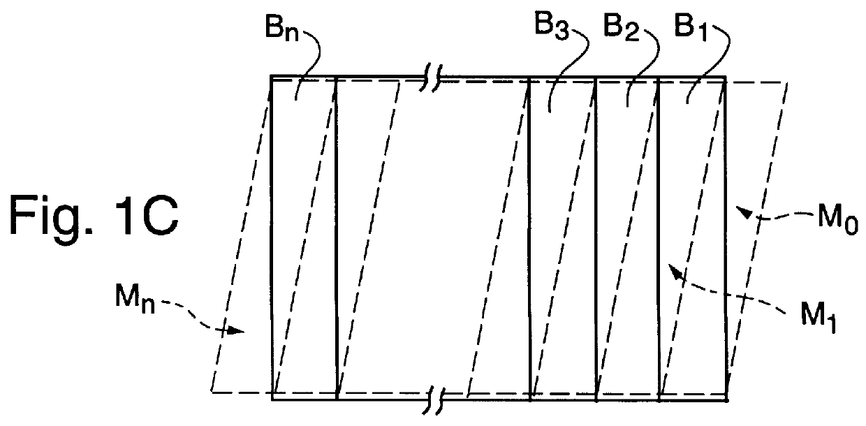
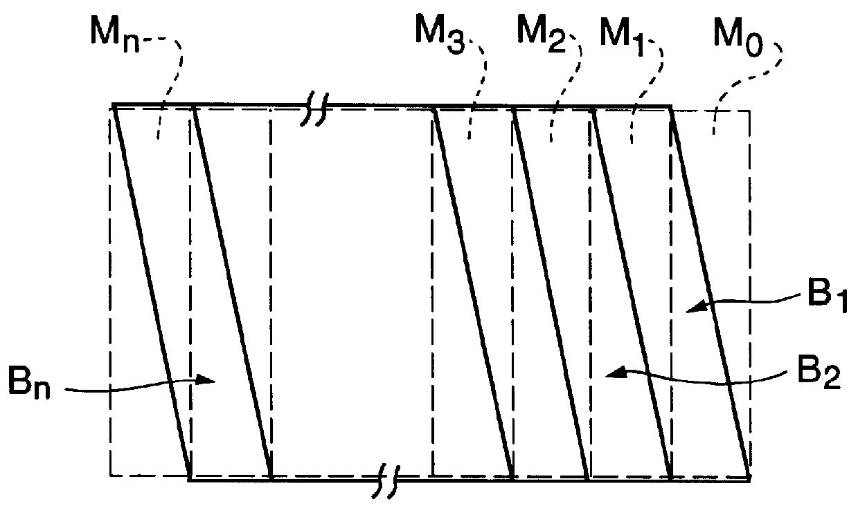
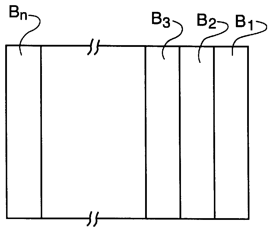
FIGS. 1A-1C show a concept of image modification, the core of the present invention. FIG. 1A shows image information in the form of a regular quadrangle memorized in the image treating apparatus, consisting of n vertically extending bands, B1 to Bn. If this image information is output into the exposure unit in this form, then the recorded image will be inclined as shown in FIG. 10B, on the printing plate in the direction in which the exposure unit is moved. To avoid this problem, the bands B1 to Bn are rearranged and inclined as shown in FIG. 1B in a solid line, by an amount equal to the width B, but in the opposite direction, by means of the image transformer PM, and memorized. The opposite direction means the direction opposite to the direction in which the exposure unit is moved and is, at the same time, opposite to the direction in which the recorded image is inclined in FIG. 10B. If the parallelogram made up of the inclined bands B1 to Bn is covered by vertical bands as indicat...

second example

FIG. 8 is a constitutional diagram of a second example of the present invention illustrating a single beam system. The parts identical with those in FIG. 2 are given common reference numerals. In the following description, emphasis is put on the parts that differ.

The laser beam emitted from laser beam source 16 is on-off controlled with the image information of image modulator PM by AOM 21. This laser beam enters a deflector 23 (i.e., the exposure unit of the second example) and is controlled to be deflected by an amount of the bandwidth B only (128 dots, for instance). The beam controlled to be deflected by the deflector 23 records the bands B1, B2, Bn to form a recorded image 28 on the printing plate 4 via a lens 24.

There is provided a deflector-driving circuit XG to drive deflector 23. An audio-optical deflector AOD may be used as the deflector. The AOD is an exposure unit that changes the lattice interval by means of high frequency, diffracts the incident beam, and accomplishes ...


PUM


Abstract

A recorded image is distorted on a printing plate when an image information for a computer is recorded in the form of a band with a band width of a plurality of image elements on a printing plate wound around a drum. This invention provides an undistorted recording on the printing plate, made possible by an arrangement that has a printing plate wound around a drum in the form of a right circular cylinder, an exposure unit that uses a light beam to record image information in the form of a band on the printing plate, a moving mechanism to move the exposure unit by one band width in the direction of the drum axis in relation to the drum while the drum makes a revolution, an image treating apparatus with the image information stored in the form of a right quadrangle, and an image modulator to rearrange and slant each band of image information readout from said image treatment apparatus by one band width in the opposite direction to the movement of said moving mechanism.

Description

The present invention relates to an apparatus for exposure of printing plates and more particularly to an arrangement for recording image information, on a printing plate wound around a drum, according to image signals from a computer.DESCRIPTION OF RELATED ARTThe recent progress of computer information processing and image treatment technologies has found its way into such fields as newspaper printing, bringing about development of a method of drawing an image directly on printing plates by laser beams in accordance with signals from the computer (as opposed to by way of the photographic film). The printing plate known in the printing industry as PS plate or pre-sensitized aluminum base plate, is widely used as a printing plate material for the purpose.Hitherto, a drum-rotating system known as facsimile apparatus has been used to draw an image on such a printing plate. Laser beams are applied in the process of image drawing on the plate around the drum. To raise the drawing efficie...

Claims


Application Information

Patent Timeline
IPC IPC(8): B41B19/00G03F7/24H04N1/047H04N1/191H04N1/06G03F7/20B41C1/00
CPCB41B19/00G03F7/24H04N1/0473H04N1/0671H04N2201/04787H04N1/1911H04N1/06
Inventor OKAMURA, YUICHIWATANABE, TAKEMI
Owner KANEDA KIKAI SEISAKUSHO
Why Eureka
Try Eureka