Dual cylinder manifold

a dual-cylinder, manifold technology, applied in the field of manifolds, can solve the problems of requiring the diver to have two regulators, unable to rely on a diving computer, and inability to accurately provide vital information to the diver

Inactive Publication Date: 2000-07-04
PRESTON PAUL CHRISTOPHER
View PDF21 Cites 19 Cited by
  • Summary
  • Abstract
  • Description
  • Claims
  • Application Information

AI Technical Summary

Problems solved by technology

The primary disadvantages with the redundant method are that it requires the diver to have two regulators, which are costly, and to juggle with two regulators throughout the dive as well as at the time the switch is made from one cylinder to the other.
Another disadvantage of the redundant dual tank system is that it makes it impossible to rely on a diving computer.
Unless the diving computer receives constant input from both tanks simultaneously, it cannot accurately provide a diver with vital information that may include, inter alia, the amount of dive time left or a decompression schedule.
One problem with the H-shaped manifold approach is it introduces moisture into the cylinders when refitting with the specialized valves.
Corrosion on the inside of a cylinder is very undesirable because it will enter and clog the breathing system.
Another problem with the rigid H-shaped manifold is that the steel band type of harness must be used to hold the two cylinders in a fixed position relative to one another because any unsynchronized movement of the cylinders would exert stress upon the cross pipe and cylinder valve connections causing an air leak and/or damage to the cylinder valves or cross pipe.
Utilizing a steel band type of harness to hold the two cylinders together is less desirable because they cost more, must be of the proper size for the cylinders being used, are heavier, and require tools and a significant amount of time to bind to the cylinders.
Other types of cylinder harnesses, such as those employing bands with hook and loop type fasteners that weigh less, cost less, fit around nearly any sized cylinder, are quick to install and do not require tools, cannot be used to hold the cylinders together when a rigid H-shaped manifold described above is used.
The need for specialized cylinder valves and a steel harness make dual cylinder diving with an H-shaped manifold system very inconvenient.
It means that a diver will probably have t

Method used


Image

  • Dual cylinder manifold
  • Dual cylinder manifold
  • Dual cylinder manifold

Examples


example 2

Manifold Example 2

Referring now to FIGS. 8-15, a second preferred embodiment of the manifold of the present invention is now disclosed that is directly connectable with either a DIN converter or yoke and yoke nut connector, and, a DIN regulator or DIN to scuba adaptor. Said second preferred embodiment comprises a manifold comprising of at least a first interconnector 8 (FIGS. 8, 11, and 15), at least one hose member 10 (FIG. 9), and a second interconnector 9 (FIGS. 10, 12, and 15). The description of the hose member in this example is the same as the hose member of Example 1 described above.

A first inlet portion 17 of first interconnector 8 and a third inlet portion 42 of second interconnector 9 are similarly constructed to possess, respectively, a male fitting 20a and 20b that can be twistably fastened with a yoke nut (which is subsequently teamed with a yoke clamp and mounted on a scuba cylinder valve), and alternatively can be twistably fastened with a DIN converter (which is sub...

example 3

Manifold Example 3

A third preferred embodiment (not depicted) of the present invention is now described that is directly connectable to two scuba cylinders with the use of yoke, and to a DIN regulator or a DIN to scuba adaptor. Generally, said third preferred embodiment includes a flexible hose member interposedly connected to a first interconnector and a second interconnector, a yoke clamp connector and a C-shaped yoke clamp connector all made and used in a manner similar to that disclosed above in Examples 1 or 2 as further described below.

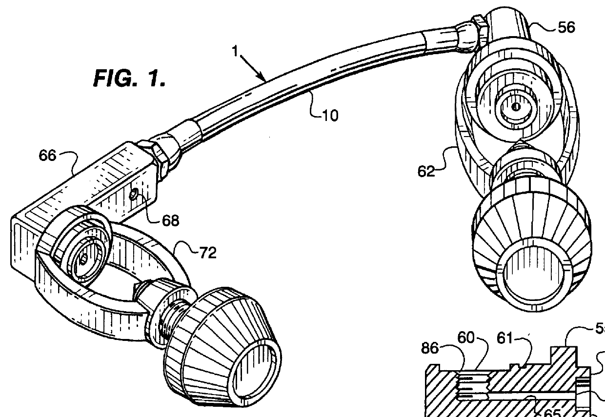
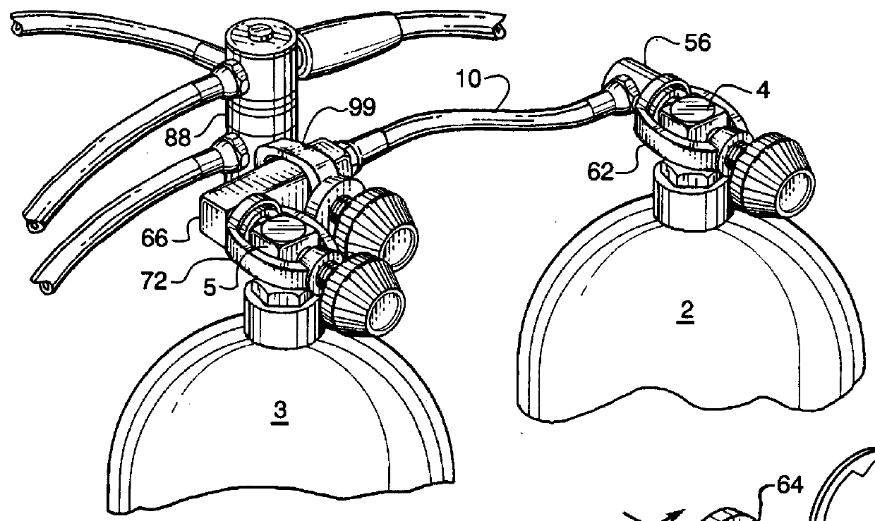
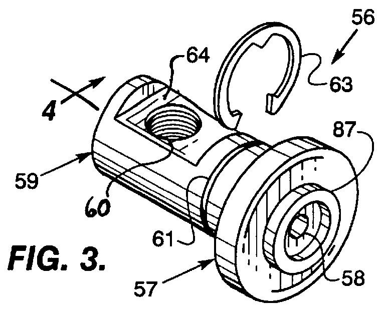
In particular, said hose member, said first interconnector, said yoke clamp connector, and said C-shaped yoke clamp connector of the instant embodiment are all like analogous members of said first preferred embodiment depicted in FIGS. 1-7 and 9 and described in Example 1 above. Said second interconnector of the instant embodiment is similar to the second interconnector of said first preferred embodiment in that said instant second interconnecto...

third embodiment

In use, the first and second interconnector of said third embodiment are connected to two scuba valves, respectively, with the yoke clamp connector and the C-sharped yoke connector, the second outlet can directly receive a DIN regulator. The use of the instant embodiment can be enhanced with adaptors. If a DIN to scuba adaptor is connected to the second outlet portion it may then accept a scuba regulator. The first and third inlet portions could be connected to dual DIN cylinders if those cylinders are adapted with DIN to scuba adaptors.


PUM


Abstract

A dual cylinder manifold comprising a flexible, high pressure hose member connected between a first and a second interconnector that funnels pressurized air from two cylinders containing pressurized air to a single regulator. In operation, the first interconnector is attached to a first cylinder valve, the second interconnector to the second cylinder valve, and a regulator attached to the second interconnector. The hose member may be removably connected to the interconnectors so that it can be replaced with another hose member if desired. The manifold may also include valve connectors attached to the interconnectors for connecting to the cylinder valves, a valve adaptor for adapting the second interconnector to receive a regulator of differing connecting design where necessary, a valve connector for making the intended regulator compatible with the second interconnector, or combinations thereof. The manifold may also be provided as a kit having removable or interchangeable components for constructing a several possible manifolds, each connectable to differing dual tank systems.

Description

1. Field of the InventionThe present invention pertains to the field of self contained underwater breathing systems and particularly relates to a manifold with a flexible hose that when connected to the cylinder valves of two cylinders (or tanks) containing compressed gas can funnel the gas therefrom to a single regulator.2. Description of Related ArtCurrently, divers double their bottom time by breathing off two cylinders containing pressurized air instead of one. One way of doing this is to simply attach separate regulators to each of the cylinder valves on the two cylinders thereby creating a redundant dual cylinder underwater breathing system. When the first cylinder empties, the diver would then open the cylinder valve on the second cylinder, retrieve the second regulator, abandon the first regulator, and breathe from the second regulator / cylinder instead of the first. The primary disadvantages with the redundant method are that it requires the diver to have two regulators, whi...

Claims


Application Information

Patent Timeline
IPC IPC(8): A62B9/00A62B9/02B63C11/22B63C11/02F16K1/30F16K1/00
CPCA62B9/02B63C11/22F16K1/307F16K1/308
Inventor PRESTON, PAUL CHRISTOPHER
Owner PRESTON PAUL CHRISTOPHER
Why Eureka
Try Eureka