Electrical connection terminal assembly and tilt washer

a technology of electric connection and terminal assembly, which is applied in the direction of threaded fasteners, washers, screws, etc., can solve the problems of lack of reliability, difficult use, and high manufacturing cost, and achieve the effect of simplifying the construction of the terminal block and being easy and inexpensive to manufactur

Inactive Publication Date: 2000-07-04
SWICK E GRANT
View PDF15 Cites 35 Cited by
  • Summary
  • Abstract
  • Description
  • Claims
  • Application Information

AI Technical Summary

Benefits of technology

The device of the present invention uniquely and elegantly solves most of the problems inherent in the prior art devices by designing the tilt washer in a manner so that it freely tips relative to the undersurface of the screw head at locations proximate the axial center line of the screw. This novel construction enables the washer to tilt in a manner to effectively grip both the large and small diameter wires which are disposed on either side of the axial center line. To enhance the gripping abilities of the washer, the undersurface thereof is provided with uniquely configured and arranged gripping projections which positively and securely grip both the large and small diameter wires.
In using the generally rectangular shaped tilt washers of the character described in the parent application, it has been determined that, because of the novel design of certain of the wire gripping means of these devices, the tilt washer does not exhibit any tendency to rotate relative to the electrical wires after the gripping means has been brought into gripping engagement with the wires. Apparently the rather small contact area with the wires coupled with the clamping force exerted on the washer by tightening the screw imposes a relatively high pressure on the wire in the contact area thereby insuring a positive biting engagement with the comparatively soft electrical wires. this biting engagement is sufficient to prevent sliding, rolling or rotation of the wires relative to the tilt washer and relative to the terminal block as the connector screw is tightened. This being the case, the present inventor has concluded that in some instances the tilt washers can advantageously be made circular rather than rectangular thereby eliminating any need to orient the washer relative to the terminal block.
It is an object of the present invention to provide a terminal clamping assembly of the character that will simultaneously accommodate and securely grip one or more conductor wires of substantially different diameters.
Another object of the invention is to provide a terminal connector assembly which is of a simple, straight-forward design and one that can be easily and inexpensively manufactured in large volume.
Another object of the invention is to provide a tilt washer as described in the preceding paragraphs which is easy and inexpensive to manufacture in very large quantities and requires no means on the terminal block to prevent washer rotation thereby further simplifying the construction of the terminal block with which the washer is used.

Problems solved by technology

For example, some are unduly complex, are difficult to use and are expensive to manufacture.
Others lack in reliability in that they do not positively grip wires of different sizes.
Because the tilt washers in the prior art devices typically pivot about points located closely adjacent the edge of the shank of the screw and closely adjacent the center of the larger wire, the washer often cannot be effectively forced into secure clamping engagement with the small wires.

Method used


Image

  • Electrical connection terminal assembly and tilt washer
  • Electrical connection terminal assembly and tilt washer
  • Electrical connection terminal assembly and tilt washer

Examples


Embodiment Construction

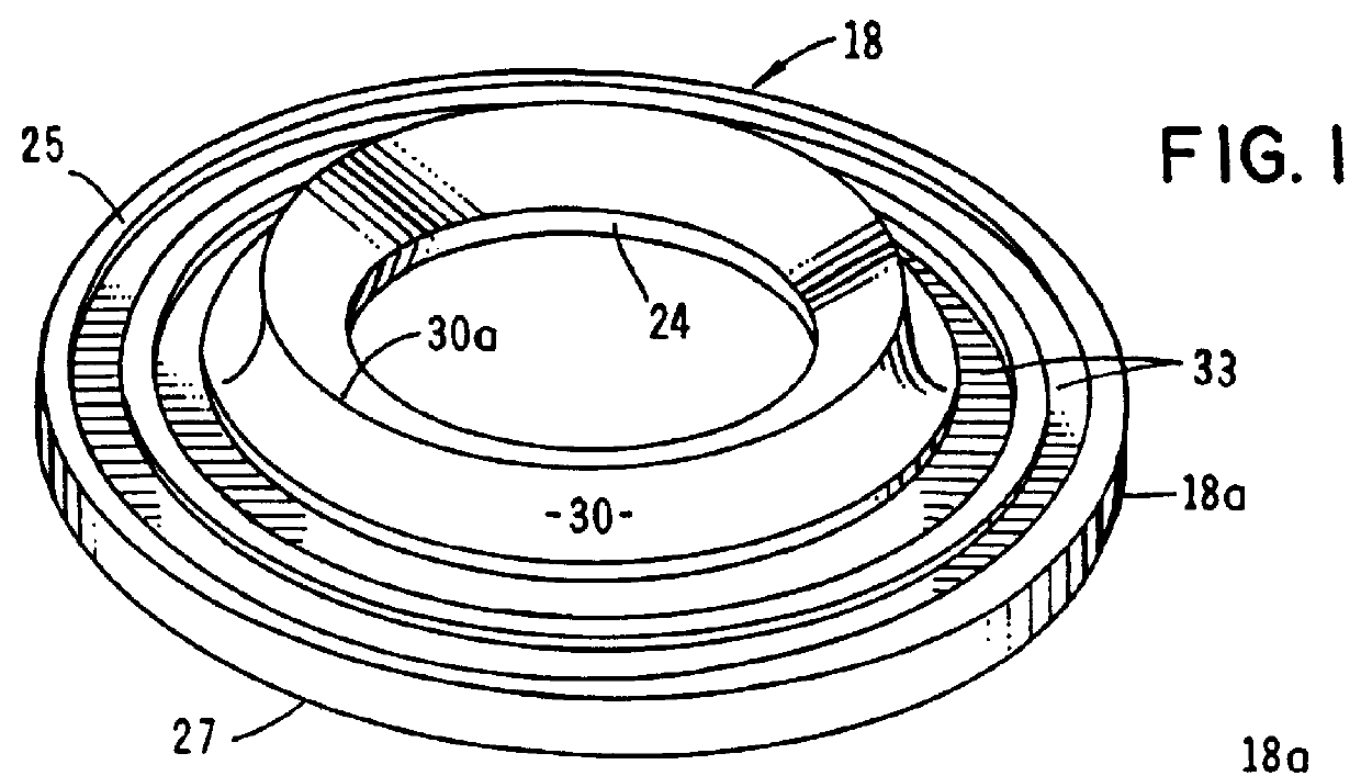
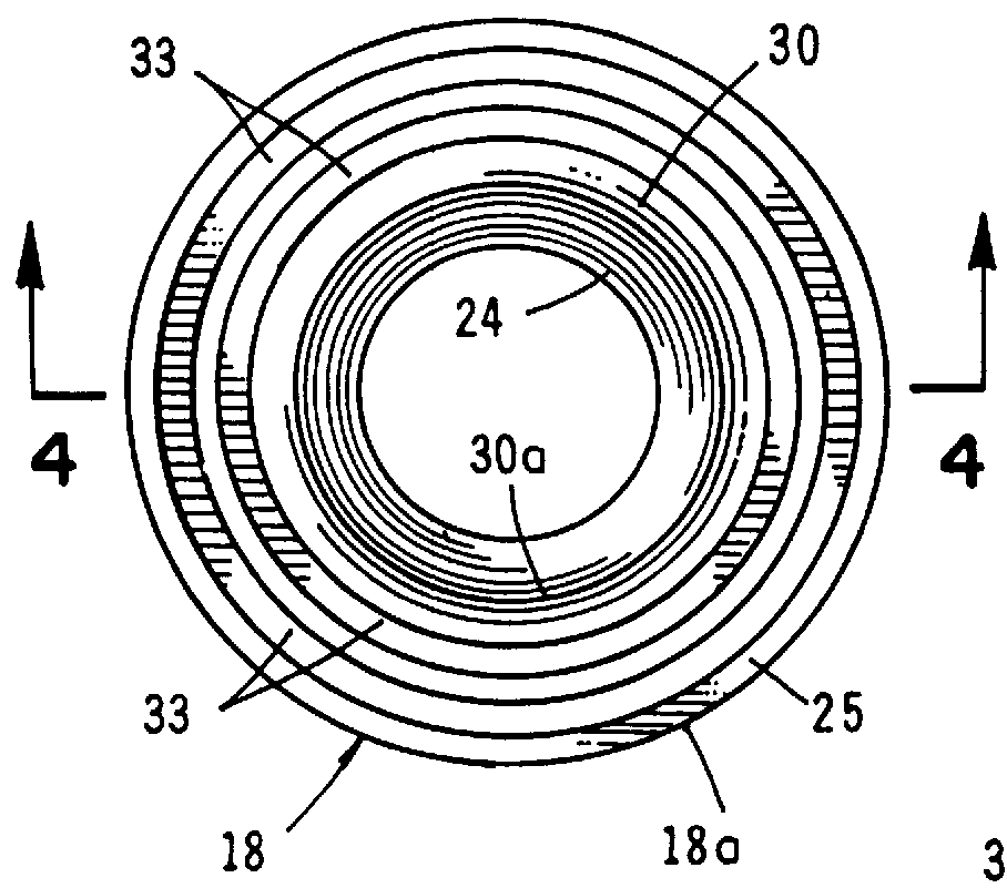
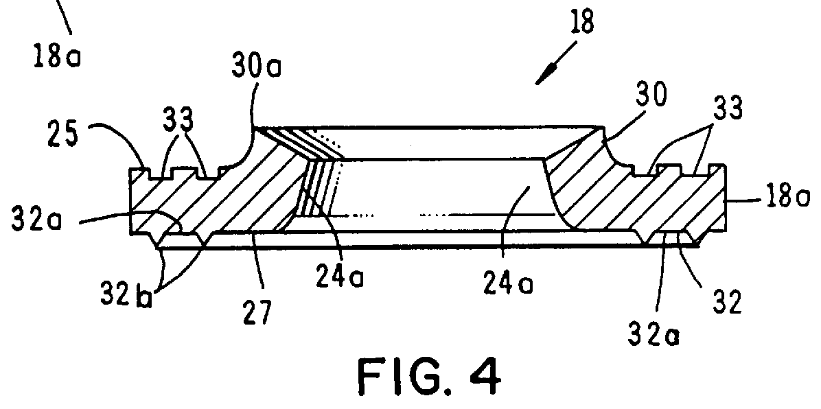
Referring to the drawings and particularly to FIGS. 1 through 5, one form of the tilt washer and electrical connector assembly of the present invention is there illustrated. This form of the invention is similar in many respects to that described in the parent application, Ser. No. 08 / 155,387, which is incorporated herein by reference. However, the tilt washer of the present invention is non-rectangular in plan rather than being rectangular and includes gripping means of a somewhat different orientation than those provided on the generally rectangular shaped tilt washers.

As before, the embodiment of the invention depicted in FIGS. 1 through 5 includes a threaded member or screw 12 of the general configuration shown in FIG. 5 having a threaded shank portion 12a and a head portion 12b. Head portion 12b has a generally flat, annular-shaped undersurface 12c and is provided with a tool-engaging slot 12d. Slot 12d can be a standard screw driver slot, a "Phillips" slot, a combination there...


PUM


Abstract

An electrical terminal clamping assembly of the character that will simultaneously accommodate and securely grip one or more conductor wires of substantially different diameters. The assembly includes a threaded terminal screw and a uniquely configured generally circular shaped clamping plate or tilt washer which is adapted to freely tilt relative to the undersurface of the head of the terminal screw in a manner to move gripping projections provided on the undersurface of the washer into secure clamping engagement with a wire of large diameter disposed on one side of the axial center line of the terminal screw and into secure clamping engagement with a wire of much smaller diameter disposed on the opposite side of the axial center line. The undersurface of the tilt washer is provided with several different types of uniquely configured gripping protuberances that provide multiple contact points for firmly gripping the different diameter conductor wires which are disposed on opposite sides of the terminal screw.

Description

The present invention relates generally to terminal clamp assemblies for clamping conductor wires of different sizes to a terminal block. More particularly, the invention concerns an electrical connection terminal assembly that includes a tilt or teetering washer of novel construction that tilts relative to the terminal screw proximate the axial center line thereof.DISCUSSION OF THE INVENTIONA number of different types of terminal clamp assemblies have been suggested in the past. Typically, the prior art assemblies comprise a screw and a clamping plate which is loosely mounted on the screw shank for tilting or teetering relative to the shank to accommodate wires of different sizes. Many of the prior art devices incorporate a rib structure at the undersurface of the washer to concentrate a clamping pressure on the conductor wires in an attempt to insure a positive and secure electrical contact.In certain prior art devices, tiltability of the clamping plate or tilt washer has been ach...

Claims


Application Information

Patent Timeline
Patent Type & Authority Patents(United States)
IPC IPC(8): H01R4/28H01R4/30H01R4/44H01R4/38
CPCH01R4/304H01R4/44Y10S411/959
Inventor SWICK, E. GRANT
Owner SWICK E GRANT
Why Eureka
Try Eureka