Magnet valve with integrated check valve

a check valve and magnet valve technology, applied in the direction of valve housings, magnetic bodies, braking systems, etc., can solve the problem of relatively high cost of known magnet valves

Inactive Publication Date: 2000-07-04
ROBERT BOSCH GMBH
View PDF2 Cites 32 Cited by
  • Summary
  • Abstract
  • Description
  • Claims
  • Application Information

AI Technical Summary

Problems solved by technology

The known magnet valve is relatively expensive, because its housing and the disk on the bottom must be made by metal-cutting machining in an expensive way, and the closing member of the check valve and the retaining part must be inserted into the disk and the thus-supplemented disk must be inserted into the housing and secured therein by a wedged connection.

Method used


Image

  • Magnet valve with integrated check valve
  • Magnet valve with integrated check valve
  • Magnet valve with integrated check valve

Examples


Embodiment Construction

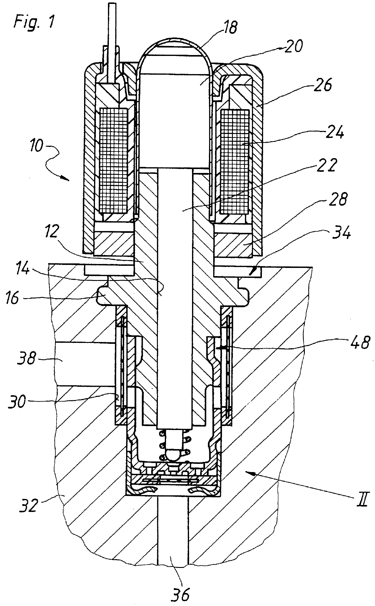
The magnet valve 10 of the invention, shown in FIG. 1, has an approximately rod-like base body 12 with an axial through bore 14 and an annular collar 16, integral with the base body, in its middle region. A valve dome 18 is mounted on one face end of the base body 12, and an armature 20 is axially displaceably received in the dome. A valve tappet 22, which reaches through the through bore 14 of the base body 12, is connected to the armature 20.

The valve dome 18 is surrounded by a coil 24, which in turn is surrounded by a cup-shaped yoke 26, into whose open face end a yoke bottom 28 in the form of a perforated disk is inserted. For actuation of the magnet valve 10, current is supplied to the coil 24, and as a result, in a manner known per se, the armature 20 is moved axially toward the base body 12. The valve tappet 22 is displaced along with the armature 20.

The annular collar 16 of the base body 12 is spaced apart from the yoke bottom 28; the base body 12 protrudes axially out of th...


PUM

PropertyMeasurementUnit
outer circumferenceaaaaaaaaaa
diameteraaaaaaaaaa
currentaaaaaaaaaa

Abstract

PCT No. PCT/DE97/02698 Sec. 371 Date Sep. 13, 1999 Sec. 102(e) Date Sep. 13, 1999 PCT Filed Nov. 17, 1997 PCT Pub. No. WO98/40258 PCT Pub. Date Sep. 17, 1998A magnet valve having a rod-like base body for insertion into a stepped bore of a hydraulic block through which a valve tappet reaches a valve closing ball and on whose face end remote to an armature a cup-shaped sleeve is mounted. A valve seat of the magnet valve is embodied on the bottom of the cup-shaped sleeve. In order to make a large flow cross section available for a flow through the magnet valve in one flow direction, a check valve is integrated with the magnet valve and that to this end flow openings are disposed on an imaginary circle in the bottom of the cup-shaped sleeve. The openings are closed by an annular valve closing body of the check valve. The magnet valve of the invention is intended particularly for use as a brake pressure buildup valve for a wheel brake cylinder of a slip-controlled vehicle brake system.

Description

PRIOR ARTThe invention relates to a magnet valve with an integrated check valve. The magnet valve is intended for use as a brake pressure buildup valve, preceding a wheel brake cylinder, for a slip-controlled hydraulic vehicle brake system.One such magnet valve is known from European Patent Disclosure EP 0 673 815 A3. Its housing is embodied as a cup-shaped sleeve with a two-piece bottom, and into this bottom a disk is inserted which has a central through bore with a valve seat on the top for an armature-actuated valve closing body. Laterally beside this flow opening, the disk has a second flow opening with a valve seat on the underside for a check valve. The flow openings have approximately the same diameter. A ball--or plate--like closing member of the check valve is received in a turned recess of the disk. A retaining part for the closing member is also located in the turned recess and is made from thin-walled sheet metal.The known magnet valve is relatively expensive, because it...

Claims


Application Information

Patent Timeline
Patent Type & Authority Patents(United States)
IPC IPC(8): B60T8/36F16K27/02F16K31/06B60T15/36
CPCB60T8/363B60T8/365F16K27/0245F16K31/0655F16K31/0665F16K27/029
Inventor SIEGEL, HEINZ
Owner ROBERT BOSCH GMBH
Why Eureka
Try Eureka