Method and device for optically reading a document model with a scanner and for printing a recording medium with a printer

a document model and scanner technology, applied in the direction of printing, instruments, other printing devices, etc., can solve the problems of not always easy to fill out pre-printed forms with typewriters, difficult to precisely position typewriters on the provided field or lines of forms, and a lot of effort on the part of recipients to decipher handwriting

Inactive Publication Date: 2000-07-11
BAUMANN FRIEDRICH ERWIN
View PDF4 Cites 15 Cited by
  • Summary
  • Abstract
  • Description
  • Claims
  • Application Information

AI Technical Summary

Benefits of technology

Since the document model, which is identical to the recording medium, is printed without leaving the device between the scanning step and the printing step, a double manual feeding of the document model is not necessary. Thus the aforementioned mismatch does not occur. It is possible, however, for the document model to be introduced into the device already askew. In this case a software program, which displays the scanned document model on a data display device of a computer, in particular on a screen of a personal computer, shows the scanned document model on the screen also in an askew position. So that the scanned document model visible on the screen can be easily filled in with data, for example using a data processing program, the scanned document model has to be moved from the said askew position into a defined position. This can be achieved using software in that tools are provided with which the document model on the screen is shifted in an X and / or Y direction, with which the document model can be rotated about a given software-defined pivot point, and with which the displayed document model can be enlarged or reduced in size.
Now when the document model is in a defined position, preferably aligned with the screen axes, it can be easily completed with characters, graphic symbols and / or other objects. Characters, symbols and / or objects can thereby be displayed on the screen in a desired position aligned with the document model. For example, empty fill-in frames can be defined as objects, which can then be completed with written characters or other information. Such fill-in frames have the advantage of making it possible to fill out forms of the same kind more quickly and more easily in that the cursor only has to jump to the fill-in frames. The sizes of fields and the types of script here can already be predefined. Fill-in frames of this kind can also be stored as files belonging to a very specific document model.
A reduction in the size of such a unit can be achieved in that the transport device is designed in such a way that the document model, or respectively the recording medium, can be transported forwards and backwards inside the device. A document model can then be completely read with the scanner, then transported back until the foremost end of the document model lies immediately in front of the printer in order to be then printed with the completed data. Through such a forwards / backwards change-over of the conveying device of the transport apparatus it is possible to reduce to a minimum the aforementioned spacing between the scanner and the printer in a second embodiment.
A straight transport path has moreover the advantage that relatively thick, or respectively relatively stiff, documents can also be processed faultlessly.
It is important to ensure that during the entire processing step scanning-printing the document model is not shifted with respect to its initial position, or does not slip on the transport element, thereby deviating from the transport direction. This can be relatively easily achieved in all the mentioned embodiments by means of contact pressure springs or pressing plates with which the document model is held on the support tray or is pressed against the conveyor belt, or, respectively, by providing a minimal spacing of roller pairs in the transport direction.

Problems solved by technology

This can be done either by hand, which nowadays is rather inconvenient and involves a lot of effort on the part of the recipient to decipher handwriting which is not always very legible.
Moreover it is not always easy to fill out pre-printed forms with a typewriter since limits are imposed by the form's thickness or spacing and by its format.
Moreover it is time-consuming and difficult to position the typewriter precisely on the provided field or lines of the form.
Now if one tries to complete an original form with a computer and printer, one is confronted with great difficulties.
Even if it seems obvious to develop a software program which allows a scanned original form to be displayed on a screen and to be completed with supplementary data in the desired places, the original form then being fed into the printer, and the printer being so controlled that only the supplementary data are printed, the mentioned difficulties cannot be overcome.
Through the double handling of the original form, once during feeding of the form into the scanner and a second time during feeding of the form into the printer, there occurs an almost unavoidable, undesirable mismatch between the form position in the scanner and in the printer.
This results in the data completed with the computer not being printed exactly in the place foreseen therefor, but rather offset.
This is annoying since either a new form to be filled out must be obtained from the responsible office, or the responsible office receives the imprecisely completed form, which is difficult to read, and which is certainly not readable by machine.
This necessarily leads to relatively large scanner / printer units.
On the other hand, in a scanner / printer unit with this kind of design the transport of relatively thick and / or stiff forms may not be entirely unproblematical, owing to the turning around.

Method used


Image

  • Method and device for optically reading a document model with a scanner and for printing a recording medium with a printer
  • Method and device for optically reading a document model with a scanner and for printing a recording medium with a printer
  • Method and device for optically reading a document model with a scanner and for printing a recording medium with a printer

Examples


Embodiment Construction

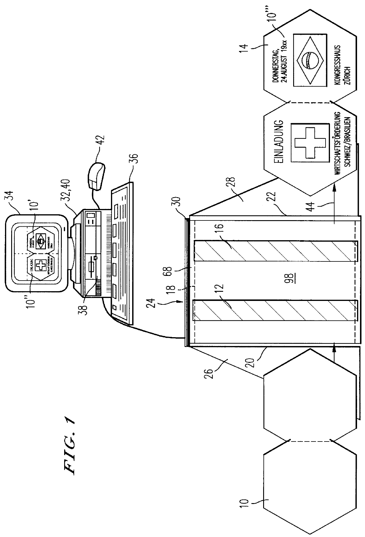
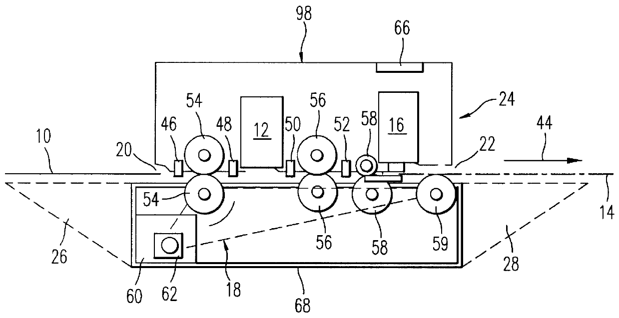
The preferred example embodiment shown in FIG. 1 of a device according to the invention comprises a scanner / printer unit 24, which, for its part, has a basic housing 68, in which a transport device 18 is disposed, in order to convey a document model 10 placed on an input tray 26, in particular a pre-printed form, from a feed device 20 along, in this example embodiment, a straight transport path determined by the transport device 18 to an output device 22 and to emit it there on an output tray 28. The transport direction is indicated by the arrow given the reference symbol 44. The transport device 18 can comprise several pairs of rollers, each with two rollers lying one above the other, pressed resiliently together, or can be designed as a conveyor belt. Disposed above the transport device 18 are a scanner 12 for optical reading of the document model 10 and a printer 16 for printing, in particular for printing the document model with supplementary data. Both devices 12, 16 are dispos...


PUM


Abstract

PCT No. PCT / CH95 / 00223 Sec. 371 Date Apr. 2, 1997 Sec. 102(e) Date Apr. 2, 1997 PCT Filed Oct. 3, 1995 PCT Pub. No. WO96 / 10881 PCT Pub. Date Apr. 11, 1996A printer / scanner unit includes a scanner for optically reading a document model and a printer to print a recording medium. The document model is transported along a transport path from a feed device to an output device of a transport device. After the scanning step, the document model is displayed on a screen and can be completed there with supplementary data, supplied, for example, by means of a data input device, such as a keyboard or a data memory. A document model which has been scanned askew, for example, can be shifted to a position which has been defined for completion with supplementary data, and can possibly be altered in size. It is foreseen that then only the data with which the document model on the screen is to be completed are transmitted to the printer, and the supplementary data are printed on the original of the document model, which was previously scanned. For that purpose, the data must be converted with transformation parameters, which the computer has obtained from the aforementioned shift of the scanned model into the defined position. The device is particularly suitable for filling in original, pre-printed forms or completing them with other data.

Description

1. Field of the InventionThis invention relates to a method for optically reading a document model with a scanner and for printing a recording medium with a printer as well as a device with a scanner for optically reading a document model and with a printer for printing a recording medium.2. Discussion of the BackgroundBoth in the business world and in private life one is often faced with the task of filling out a pre-printed form, for example a tax declaration form or an application for some event. This can be done either by hand, which nowadays is rather inconvenient and involves a lot of effort on the part of the recipient to decipher handwriting which is not always very legible. An improvement is achieved if such forms are completed using a typewriter, if such is available. This is not always the case, above all in the private sphere. Moreover it is not always easy to fill out pre-printed forms with a typewriter since limits are imposed by the form's thickness or spacing and by ...

Claims


Application Information

Patent Timeline
Patent Type & Authority Patents(United States)
IPC IPC(8): H04N1/04H04N1/00
CPCH04N1/0057H04N1/00596H04N1/00681H04N1/00702H04N1/00708H04N1/00718H04N1/00745H04N1/00785H04N1/0461
Inventor BAUMANN, FRIEDRICH ERWIN
Owner BAUMANN FRIEDRICH ERWIN
Why Eureka
Try Eureka