Video-coding device and video-decoding device

a video-coding and video-decoding technology, applied in the field of video-coding devices, can solve the problems of inability to practically transmit video information, inability to completely prevent the propagation of said error to subsequent images, and inability to properly decode whole images from image information encoded by the conventional coding method

Inactive Publication Date: 2000-07-18
SHARP KK
View PDF10 Cites 43 Cited by
  • Summary
  • Abstract
  • Description
  • Claims
  • Application Information

AI Technical Summary

Benefits of technology

In view of the foregoing problems involved in the prior arts, the present invention is made to provide a video-coding device and a video-decoding device, which are capable of assuring the necessary quality of a video sequence even if a transmission error and / or a loss of information occurs in a transmission line and preventing the propagation of decoding error to subsequent images, and further provide a video-coding device and a video-decoding device, which can effectively retransmit necessary coded information if a transmission error and / or a loss of information occurs in a transmission line.

Problems solved by technology

Accordingly, it is impossible to practically transmit video information as it is, because of necessity of a transmission line with a very wide-band transmission capacity.
However, the prior art coding method encodes a video sequence frame by frame and, therefore, a whole image may not correctly be decoded from image information encoded by the conventional coding method if any image signal should have a transmission error or loss of information, which occurred in a transmission line.
Furthermore, the prior art method uses the interframe prediction coding technique and therefore involves a problem of handing down an incorrectness occurred in a decoded image to all subsequent frames to be encoded.
However, when transmission error and / or a loss of information occurs in a transmission line, the above-mentioned prior art hierarchical coding device can enclose the decoding error within a hierarchical layer but cannot completely prevent said error from propagating to subsequent images.

Method used


Image

  • Video-coding device and video-decoding device
  • Video-coding device and video-decoding device
  • Video-coding device and video-decoding device

Examples


first embodiment

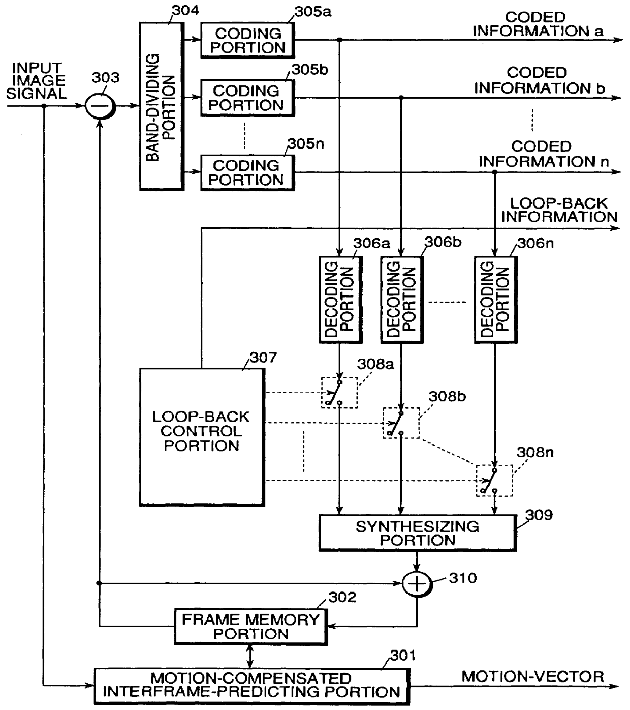
FIG. 3 depicts a video coding device for hierarchically encoding a video sequence, which is the present invention.

As shown in FIG. 3, the first embodiment of the present invention comprises a motion-compensated interframe predicting portion 301, a frame memory portion 302, a difference calculating portion 303, a band-dividing portion 304, coding portions 305a to 305n, decoding portions 306a to 306n, a loop-back control portion 307, a loop-back selecting portion 308a-308n, a synthesizing portion 309 and adding portion 310.

The above-mentioned portions of the first embodiment are described below in detail.

The motion-compensated interframe-predicting portion 301 performs motion-compensated prediction of the input image signal by reference to the preceding image signal that was coded, decoded and stored in the frame memory portion 302. This predicting portion 301 outputs motion vectors as a result and reads the predicted image signal from the frame memory portion 302.

The frame memory por...


PUM


Abstract

A video-coding device and a video-decoding device, which are capable of assuring the necessary quality of a video sequence even if a transmission error and/or a loss of information occurs in a transmission line and preventing the propagation of decoding error to subsequent images, and can effectively retransmit the necessary coded information when a transmission error and/or a loss of information occurs in a transmission line. A motion-compensated interframe-predicting portion predicts an input image by using a preceding decoded image stored in a frame memory portion and outputs motion vectors. A difference calculating portion determines a difference between the input image signal and the predicted image signal and outputs the difference as a prediction-error signal to a band-dividing portion which in turn divides the prediction-error signal into n hierarchical layers of frequency-band-components and outputs them to respective coding portions. A loop-back control portion decides whether each of the coded frequency-band-components of the coded prediction-error signal from respective coding portions is input to a synthesizing portion and outputs a decoded prediction-error signal. The predicted image signal and the decoded prediction-error signal are combined to generate a decoded image signal corresponding to the input image. The decoded image signal is used for prediction of a subsequent input image. A motion-compensated interframe-predicting portion predicts an input image by using a preceding decoded image stored in a frame memory portion and outputs motion vectors. A difference calculating portion determines a difference between the input image signal and the predicted image signal and outputs the difference as a prediction-error signal to a band-dividing portion which in turn divides the prediction-error signal into n hierarchical layers of frequency-band-components and outputs them to respective coding portions for quantizing and encoding the respective components. Buffer portions store the coded information and output the information to an external circuit. The buffers output respective frequency-band-components of the coded information according to retransmission request signals from a retransmission control portion.

Description

BACKGROUND OF THE INVENTIONThe present invention relates to a video coding device for compressively encoding a video signal by reducing redundant data contained therein and a video decoding device for decoding the compressed coded video signal and, more particularly, relates to a video coding device for hierarchically encoding a video sequence by previously performing motion-compensated interframe prediction of video frames, dividing an obtained prediction error signal into frequency-band-components and separately encoding each of the frequency-band-components and a video decoding device for decoding video signals coded by the video coding device.With recent developments of multimedia services, the image processing technique gets an increasing importance and various kinds of studies concerning to the image processing have been made in various fields of applications.In general, video information contains a very large amount of information. Accordingly, it is impossible to practically...

Claims


Application Information

Patent Timeline
Patent Type & Authority Patents(United States)
IPC IPC(8): G06T9/00H04N7/26H04N19/895
CPCH04N19/63H04N19/61H04N19/89H04N19/102
Inventor HIBI, KEIICHISATO, SEIJI
Owner SHARP KK
Why Eureka
Try Eureka