

Rotary drilling systems
- Summary
- Abstract
- Description
- Claims
- Application Information
AI Technical Summary
Problems solved by technology
Method used
Image

Examples
Embodiment Construction
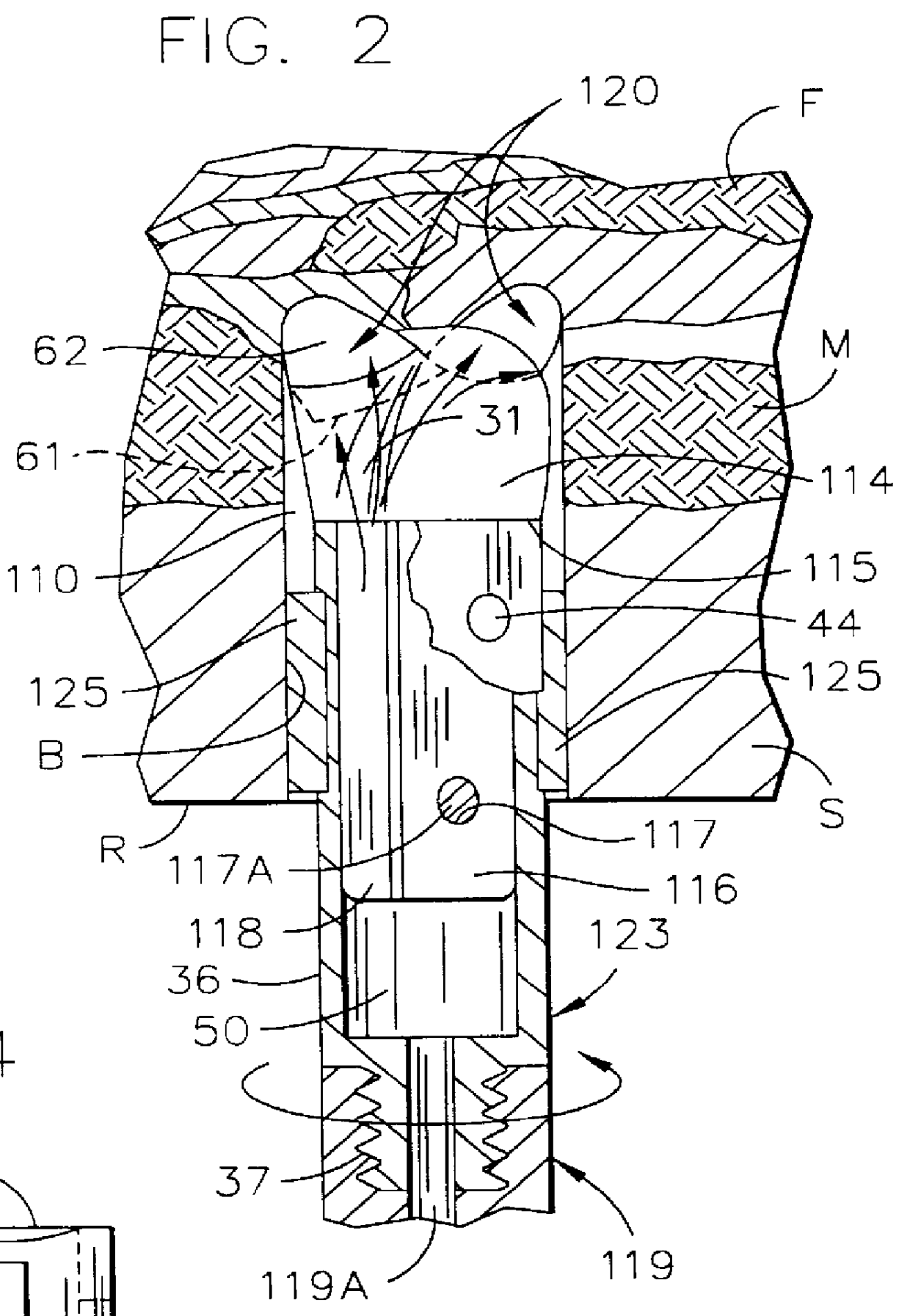
The present invention pertains generally to mining operations that include roof drilling, longwall mining and continuous mining in which water flushing is non-recoverable; and specifically the invention pertains to improvements in non-leak systems for delivering low volumes of flushing fluids while maintaining uniform and smooth bore sizing that provides better fluid flow for removing damp or muddy cuttings from the holes.
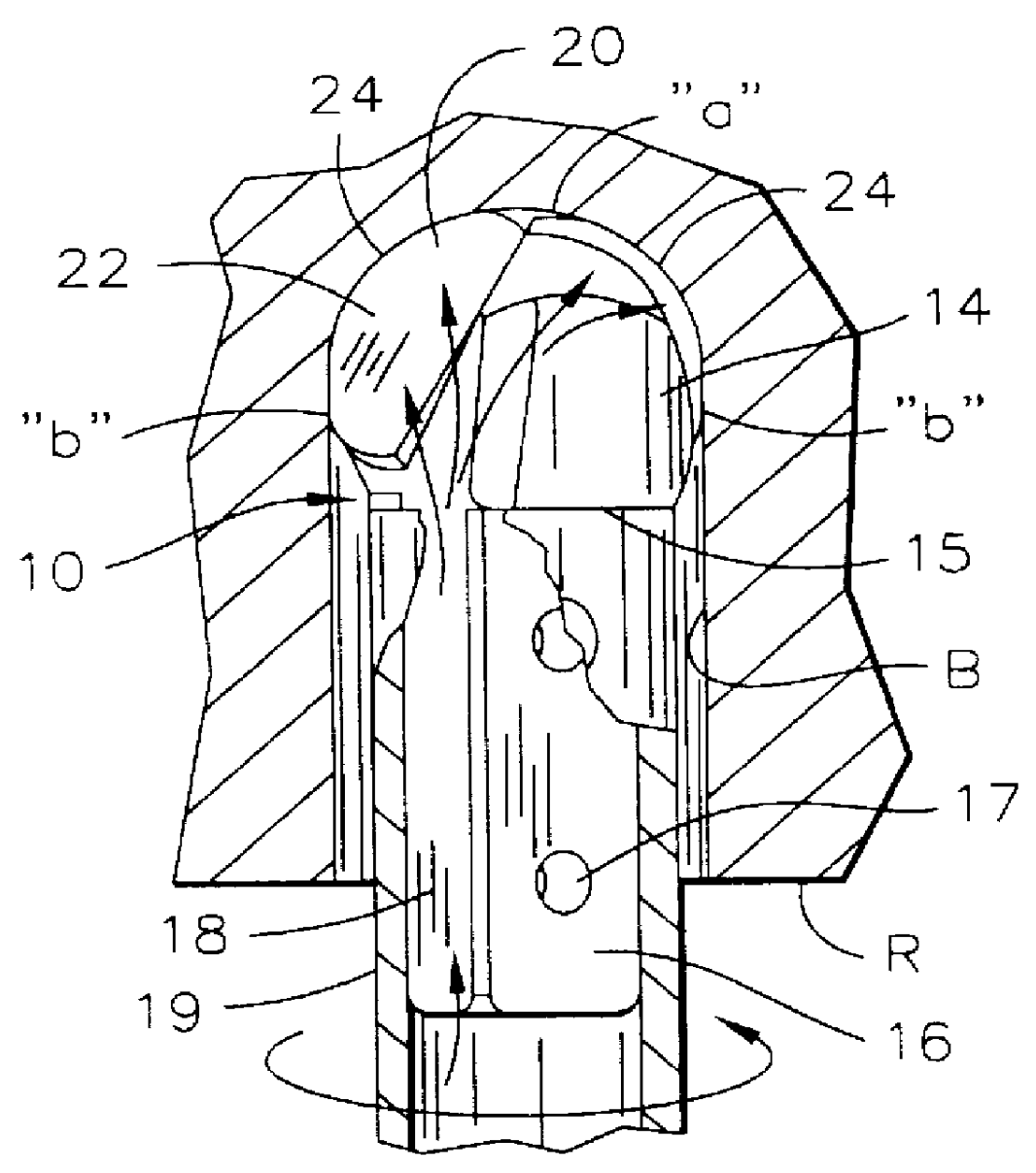
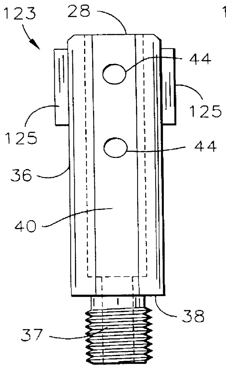
FIG. 1 shows one embodiment of my earlier non-coring roof drill bit as taught by my U.S. Pat. Nos. 5,180,022; 5,303,787 and 5,383,526--the disclosures of which are incorporated by reference herein as though fully set forth. Briefly stated, this non-coring roof drill bit 10 has a steel head portion 14 and shank portion 16 that is typically seated, at 15, on the end of a long rod drive steel 19 (119) of a drilling machine 76, such as a New Fletcher double boom roof bolter (shown in FIG. 6). The shank 16 and drive steel 19 have a complementary sliding fit and are cros...
PUM
 Abstract
Description
Claims
Application Information