Gas turbine cooling stationary blade

a stationary blade and gas turbine technology, which is applied in the direction of liquid fuel engines, vessel construction, marine propulsion, etc., can solve the problems of large amount of air consumed for cooling, the steam cooling system used in the stationary blade has not yet been put into practical use, and the cooling effect of the shroud is not considered, so as to improve the efficiency of the turbine

Inactive Publication Date: 2000-07-25
MITSUBISHI HITACHIPOWER SYST LTD
View PDF8 Cites 37 Cited by
  • Summary
  • Abstract
  • Description
  • Claims
  • Application Information

AI Technical Summary

Benefits of technology

Accordingly, in order to solve the above-noted problems, a primary object of the present invention is to provide a gas turbine cooled stationary blade in which not only cooling of an interior of a blade, but also cooling of an inner shroud is performed by steam cooling, and steam that has been used for cooling is completely recovered and returned to a steam feed source for effective utilization without the necessity of cooling air to thereby enhance the efficiency of the turbine.

Problems solved by technology

However, there is no consideration of the cooling effect on the shrouds.
The steam cooling system used in this stationary blade has not yet been put into practical use.
However, in the air cooling system shown in FIG. 5 described above, a large amount of air is consumed for cooling and the air that has been used for cooling is discharged to the combustion gas passage.
Consequently, the system suffers from a problem in that a relatively large amount of power is consumed by a compressor or a cooler.
Also, since the air that has been used for cooling is discharged into the combustion gas passage, the cooling air is mixed with the combustion gas which lowers the gas temperature resulting in a reduction of turbine efficiency.

Method used


Image

  • Gas turbine cooling stationary blade
  • Gas turbine cooling stationary blade
  • Gas turbine cooling stationary blade

Examples


embodiment 1

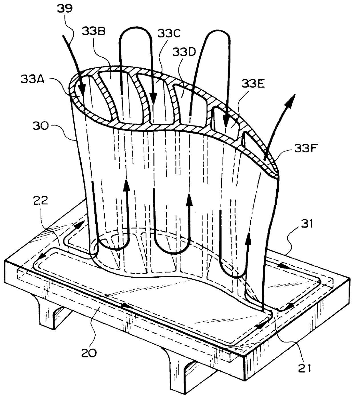
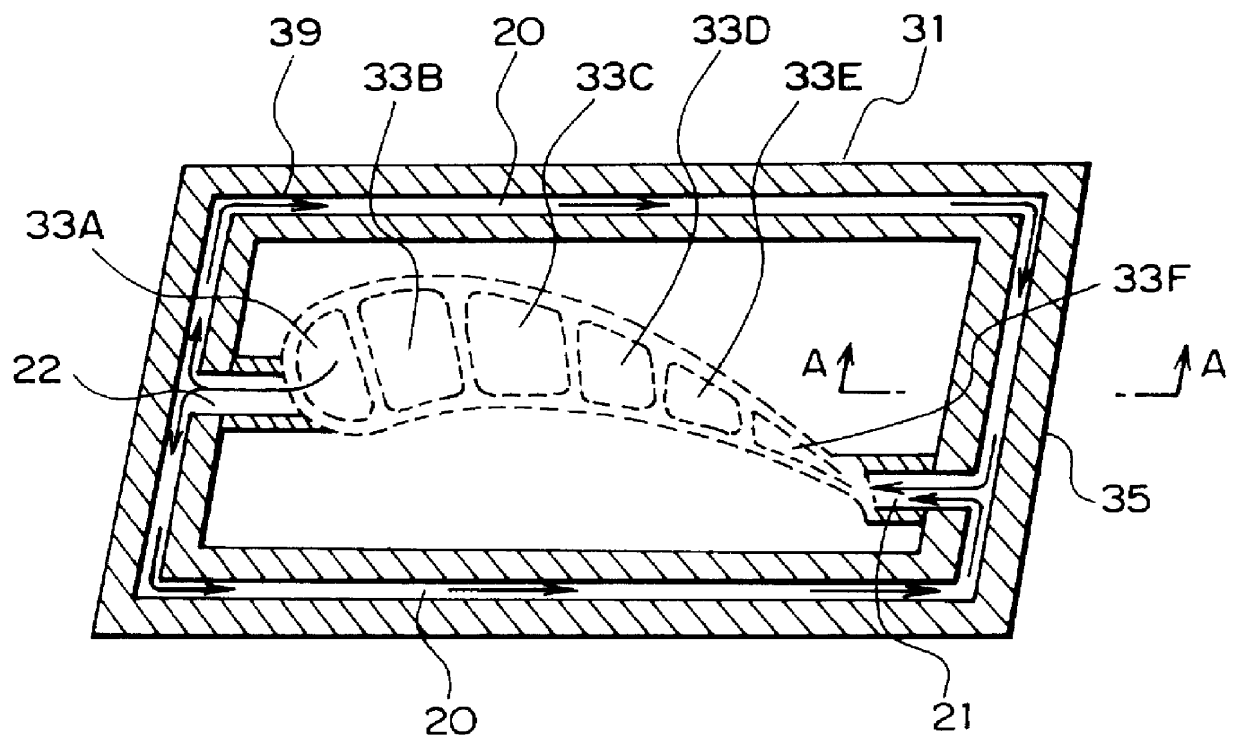
FIG. 1 is a schematic view of a cooled stationary blade for a gas turbine in accordance with an embodiment of the present invention. In the drawing, reference numerals 31 and 33A to 33F denote components having the same functions as those of the cooled stationary blade for the gas turbine shown in FIG. 4 now being developed by the present applicant, an explanation of which has been given so a detailed explanation will be omitted here. The characteristic portion of the present invention is a cooled stationary blade for a gas turbine which is under development by the present applicant and is further improved, and not only the interior of the blade 30, but also the end portion of the inner shroud 31 is steam-cooled.

In FIG. 1, the cooling steam 39 is introduced into the steam passage 33A from the outer shroud (not shown) of the front edge side of the stationary blade 30 in the same way as in the example shown in FIG. 4. The steam is introduced from the steam passage 33A to the steam pas...


PUM


Abstract

PCT No. PCT/JP98/01958 Sec. 371 Date Dec. 17, 1998 Sec. 102(e) Date Dec. 17, 1998 PCT Filed Apr. 28, 1998 PCT Pub. No. WO98/50684 PCT Pub. Date Nov. 12, 1998In a cooled stationary blade assembly for a gas turbine, an interior of a blade and an inner shroud are cooled by steam to eliminate the use of air cooling. Steam passages 33A, 33B, 33C, 33D, 33E and 33F are provided in the stationary blade 30. The cooling steam 39 is introduced from the steam passage 33A on the front edge side through an outer shroud and passes, in order, through the steam passages 33B, 33C, 33D, and 33E to flow into the steam passage 33F at the rear edge side to cool the interior of the blade, and is recovered through the outer shroud from the upper portion of the steam passage 33F. A portion of the steam from the steam passage 33A is introduced into the inner shroud 31, enters to steam passages 20 from a steam introduction passage 22, branches to the right and left through both end portions, and flows out into the steam passage 33F at the rear edge from a steam discharge passage 21. Not only the interior of the blade, but also the interior of the inner shroud 31 is cooled by the steam so that the cooling air is dispensed with.

Description

1. Technical Field of The InventionThe present invention relates to a steam cooled stationary blade for a gas turbine, and more particularly to a cooled stationary blade for a gas turbine for steam cooling both an inner shroud and the blade.2. Description of The Related Art:FIG. 5 shows a typical conventional air cooled type gas turbine stationary blade. In this drawing, numeral 40 denotes a stationary blade, numeral 41 denotes an outer shroud and numeral 42 denotes an inner shroud. Reference characters 43A, 43B, 43C, 43D and 43E denote respective air passages. Numeral 45 denotes a rear edge of the blade. Numeral 44 denotes air blowout holes at the rear edge. Reference numeral 46 denotes turbulators provided in an inner wall of each air passage 43A to 43E for enhancing heat transmission by distributing the air flow.In this air cooled type stationary blade, the cooling air 47 is introduced from the outer shroud 41 to the air passage 43A and flows to a base portion (at the inner shrou...

Claims


Application Information

Patent Timeline
Patent Type & Authority Patents(United States)
IPC IPC(8): F01D9/00F01D5/18F01D9/02F01D9/06
CPCF01D5/187F01D9/02F01D9/065F05D2240/81F05D2260/22141F05D2240/10
Inventor TOMITA, YASUOKIAOKI, SUNAOSUENAGA, KIYOSHIISHIGURO, TATSUO
Owner MITSUBISHI HITACHIPOWER SYST LTD
Why Eureka
Try Eureka