In-line method of manufacture of ostomy appliance faceplate

Inactive Publication Date: 2000-07-25
HOLLISTER INCORPORAED
View PDF9 Cites 24 Cited by
  • Summary
  • Abstract
  • Description
  • Claims
  • Application Information

AI Technical Summary

Problems solved by technology

Furthermore, high-speed production equipment often has the disadvantage of being difficult and time-consuming to convert to the manufacture of similar components di

Method used


Image

  • In-line method of manufacture of ostomy appliance faceplate
  • In-line method of manufacture of ostomy appliance faceplate
  • In-line method of manufacture of ostomy appliance faceplate

Examples


Embodiment Construction

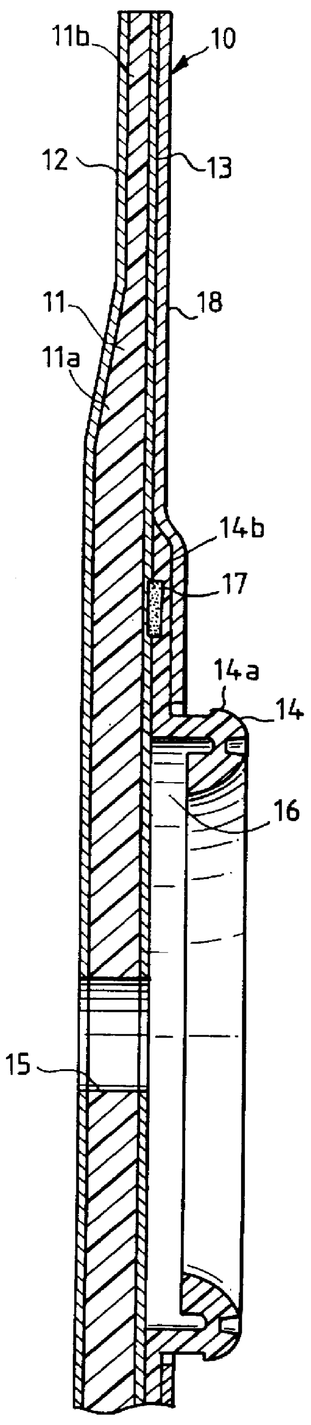
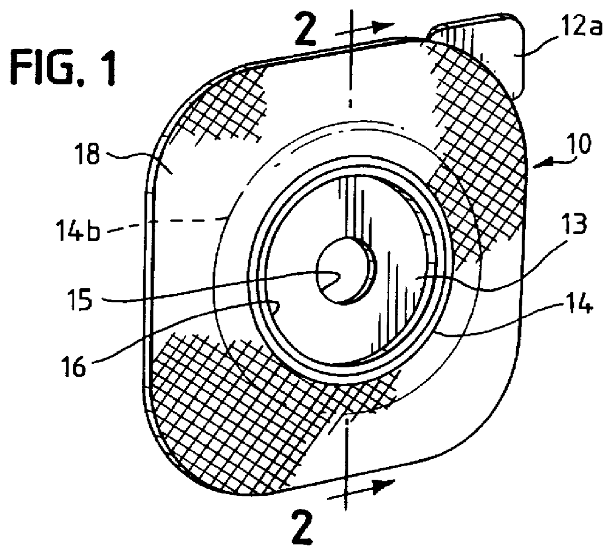
Referring to FIGS. 1 and 2, the numeral 10 generally designates a faceplate for a two-piece ostomy appliance. The faceplate as shown is generally rectangular (square) in outline with rounded corners, but other shapes, such as circular or oval shapes, may be provided. The faceplate includes a wafer or layer 11 of moisture-absorbing adhesive skin barrier material having a bodyside surface covered by a removable release sheet 12, an opposite surface covered by a thin backing film 13, and a coupling ring 14 secured to film 13.

The term "skin barrier" is widely used in the medical field, and is used herein, to refer to any of a variety of materials in which a soft, sticky, and pliant adhesive composition constitutes a continuous phase and particles of one or more liquid-absorbing and swellable hydrocolloids are dispersed throughout the adhesive and constitute a discontinuous phase. The adhesive phase contains at least one elastomer such as polyisobutylene, often in combination with one or...


PUM

PropertyMeasurementUnit
Timeaaaaaaaaaa
Flexibilityaaaaaaaaaa
Adhesivityaaaaaaaaaa

Abstract

A low-profile faceplate assembly for a two-piece ostomy appliance, and a method for manufacturing it, are disclosed. The faceplate includes a wafer of an adhesive skin barrier material and a flexible plastic coupling ring (for detachably coupling the faceplate to an ostomy pouch having a mating ring), and is distinguished by the mounting flange of the coupling ring being embedded within the faceplate. The faceplate is made by a convergence of in-line processes taking place simultaneously with an injection/compression molding operation for the skin barrier wafer as disclosed in U.S. Pat. No. 5,716,475, thereby eliminating or greatly reducing the assembly labor for the various process steps plus the handling, storing and transferring steps commonly associated with the manufacture of ostomy faceplate assemblies.

Description

BACKGROUND OF THE SUMMARYIn conventional manufacture of the faceplate assemblies for use with two-piece ostomy appliances, it is common practice to produce and store each of the several components and then join them together, often by hand, at the time of final assembly. For example, adhesive wafers are customarily manufactured by extruding skin barrier material onto a receiving web and then die-cutting and storing the wafers for later assembly with other parts or sub-assemblies needed for the final product. While it might be thought that manufacturing efficiencies are enhanced by high-speed production of each of the various components and sub-assemblies, just the opposite is believed to be the case if subsequent assembly steps occur at different locations, or at different times, and require storage, handling, and additional procedures such as inspections or re-inspections, further testing, and the like. Furthermore, high-speed production equipment often has the disadvantage of bein...

Claims


Application Information

Patent Timeline
IPC IPC(8): A61F5/443A61F5/445A61F5/448
CPCA61F5/443A61F5/448Y10T156/1084Y10T156/1089
Inventor LEISE, JR., WALTER F.BOTTEN, RONALD S.MCDONALD, JR., JOHN W.RIGAS, DEMETRIOSPASSALAQUA, JAMES J.
Owner HOLLISTER INCORPORAED
Why Eureka
Try Eureka