Reverse rotation protection for a scroll compressor using a valve means

a scroll compressor and valve means technology, applied in the direction of machines/engines, liquid fuel engines, positive displacement liquid engines, etc., can solve the problems of compressor performance drop, compressor performance drop, and abnormal pressure on the end surfaces of the involute bodies, so as to reduce the overall compressor cost

Inactive Publication Date: 2000-08-01
DAIKIN IND LTD
View PDF7 Cites 33 Cited by
  • Summary
  • Abstract
  • Description
  • Claims
  • Application Information

AI Technical Summary

Benefits of technology

On the other hand, the pressure of the outer compartment (35) increases to above that of the inner compartment (34) during the reverse operation period. The other end surface of the seal member (47) receives a force greater than a force that the one end surface receives. As a result, the seal member (47) moves towards the boss (10d) bottom wall, in other words in the direction away from the valve seat (10f). This creates a clearance between the barrier wall (25) and the seal member (47) barrier wall side end surface, such a created clearance providing communication between the clearance (50) and the inner compartment (34). As a result, the inner compartment (34) and the outer compartment (35) communicate with each other. Accordingly, the same operation effects as the foregoing invention can be obtained. In addition, there is no need of providing a concave recess in the barrier wall (25) that fits into the boss (10d) of the fixed scroll (10), which makes it possible to form the barrier wall (25) in the form of a plate. This achieves a reduction of the overall compressor cost.

Problems solved by technology

If such division of the casing internal cavity is made by the fixed scroll per se, the fixed scroll is likely to undergo bending due to differential in pressure between the discharge chamber and the suction chamber.
As a result, the compressor falls off in performance.
Both of the involute bodies undergo thermal expansion due to the fictional heat, as a result of which the forward end surfaces of the involute bodies are abnormally pressed against their respectively facing panel boards.
Much greater frictional heat is produced, therefore causing seizing in the forward end surfaces of the involute bodies immediately after the moving scroll starts rotating.
Eventually, the frictional heat causes damage to the involute bodies after an elapse of a certain period of time.
This prior art technique may be problematic.
In addition to the above-noted problem, even when the relief passage is closed by the relief valve during the correct operation period, compressed gas will go into the relief passage.
The fixed scroll will become deformed and the loss of heating will occur.
Further, due to reverse flow of the gas that entered the relief passage, the gas reexpands resulting in a drop in the compressor performance.

Method used


Image

  • Reverse rotation protection for a scroll compressor using a valve means
  • Reverse rotation protection for a scroll compressor using a valve means
  • Reverse rotation protection for a scroll compressor using a valve means

Examples


second embodiment

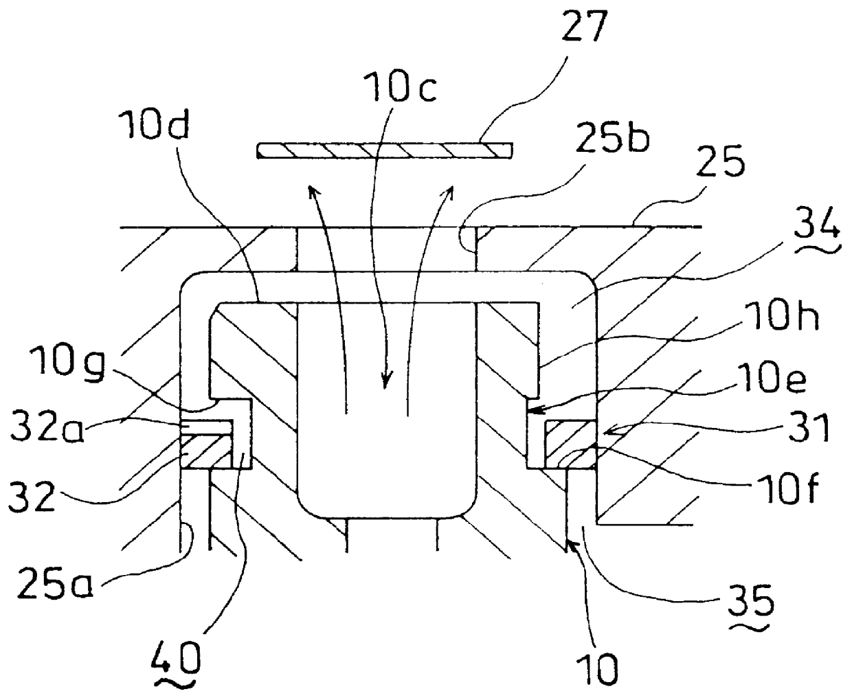
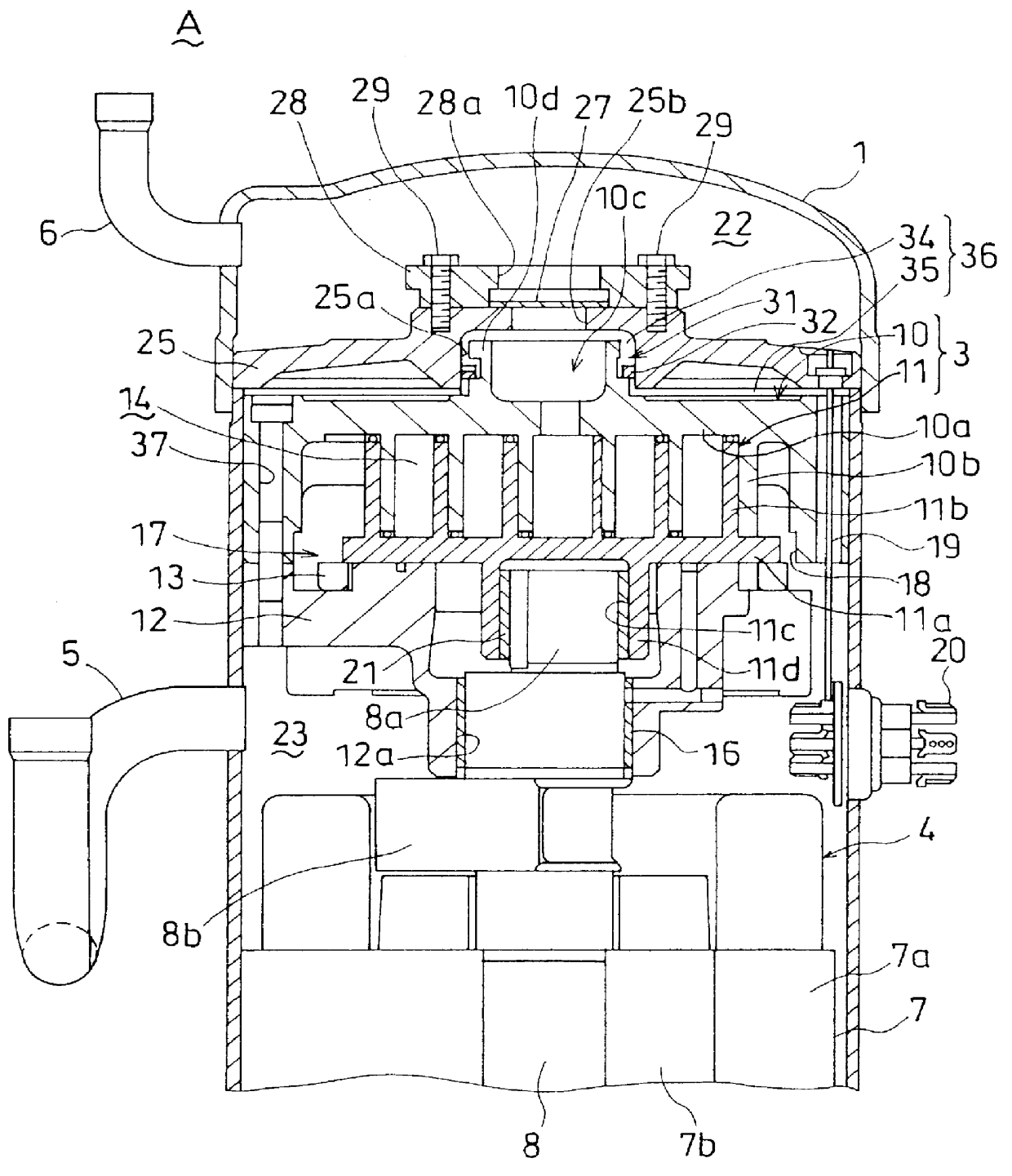
Reference is made to FIGS. 6 and 7 to describe the present invention. The same elements and portions as FIG. 1 have been assigned the same reference numerals and the detailed description thereof is not made. In accordance with the present embodiment, a stopper portion, with which the seal member (32) is brought into contact when moving away from the valve seat (10f), is formed in the concave recess (25a) inner peripheral surface of the barrier wall (25).

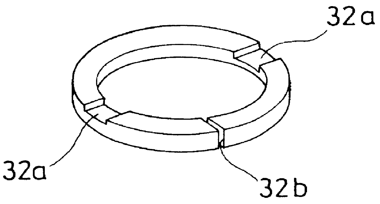
As in the first embodiment, the valve seat (10f) is formed at the boss (10d) base outer peripheral surface of the fixed scroll (10). A stopper portion (25c) is formed at the concave recess (25a) inner peripheral surface of the barrier wall (25), at an equivalent level to the stopper portion (10g) of the boss (10d) of the first embodiment. In addition, the seal member (32) is disposed between the stopper portion (25c) and the valve seat (10f), with the clearance (40) defined between the seal member (32) inner peripheral surface and th...

first embodiment

On the other hand, when the scroll compressor (A) is opposition operated, the outer compartment (35) comes to have a pressure in excess of that of the inner compartment (34). The seal member (32) then travels upwardly to be brought into contact with the stopper portion (25c) of the concave recess (25a) of the barrier wall (25), as shown in FIG. 7. At this time, since the stopper portion (25c) is located on the peripheral side of the seal member (32), this maintains the communication of the clearance (40) and the inner compartment (34). As a result, refrigerant gas flows in the same way as in the

In accordance with the present embodiment, the stopper portion (25c), with which the seal member (32) is brought into contact when the seal member (32) separates from the valve seat (10f) and moves upwardly, is formed in the concave recess (25a) of the barrier wall (25). This eliminates the need for forming a bypass passage for providing communication between the clearance (40) and the inner ...


PUM


Abstract

PCT No. PCT/JP97/01799 Sec. 371 Date Jan. 28, 1998 Sec. 102(e) Date Jan. 28, 1998 PCT Filed May 27, 1997 PCT Pub. No. WO97/45642 PCT Pub. Date Dec. 4, 1997A scroll compressor (A) includes a barrier wall (25) which divides the internal cavity of a casing (1) into a discharge chamber (22) and a suction chamber (23) and has a discharge opening (25b) for providing the communication of the compartments (22) and (23), a check valve (27) operable to prevent a flow of gas from the discharge chamber (22) into the suction chamber (23), and a scroll compression mechanism (3) which is provided in the suction chamber (23), which a space (36) left between the mechanism (3) and the barrier wall (25), for discharging compressed gas into the space (36). In addition, a valve (31) is provided in the space (36) which has a seal member (32) operable to interrupt the communication of an inner compartment (34) with an outer compartment (35) of the space (36) during the correct operation period while on the other hand providing the communication during the reverse operation period. Without suffering a drop in performance during the correct operation period, frictional heat occurring at the forward end surfaces of involute bodies (10b) and (11b) of fixed and moving scrolls (10) and (11) is positively removed to outside the scroll compression mechanism (3), thereby preventing these end surfaces from undergoing seizing.

Description

1. Technical FieldThis invention generally relates to a scroll compressor with a scroll compression mechanism made up of a fixed scroll and a moving scroll and more specifically to technology to prevent damage to the scroll compression mechanism due to opposite rotation of the moving scroll to the correct rotation direction.2. Background ArtA typical scroll compressor of this type has in a casing a scroll compression mechanism comprising two different scrolls, namely a moving scroll rotatably driven by a motor and a fixed scroll secured to the casing. The moving scroll has a panel board from which an involute body projects. On the other hand, the fixed scroll has a panel board disposed so as to face the panel board of the moving scroll. Disposed on the panel board of the fixed scroll is an involute body which engages with the involute body of the moving scroll in order that a compression chamber may be defined therebetween. Approximately centrally formed in the panel board of the fi...

Claims


Application Information

Patent Timeline
Patent Type & Authority Patents(United States)
IPC IPC(8): F04C18/02F04B49/00F04C27/00F16K15/00F04C28/26F04C28/28F04C29/12
CPCF04C28/28F04C29/126F04C28/265F04C2270/72F04C18/02
Inventor SHIBAMOTO, YOSHITAKAKAJIWARA, MIKIOYOSHIMURA, KEIJIUEDA, SHUUSAKU
Owner DAIKIN IND LTD
Why Eureka
Try Eureka