Apparatus for forming controlled density fibrous pads for diapers and the other absorbent products

a technology of fibrous pads and absorbent products, which is applied in the direction of manufacturing tools, rod connections, other domestic articles, etc., can solve the problems of uneven fiber density in the pads, especially at the ends, and the fiber distribution problems described above, and achieve the effect of reducing the number of fibers in the pads, and improving the quality of the produ

Inactive Publication Date: 2000-08-08
TONEY JERRY L +3
View PDF5 Cites 109 Cited by
  • Summary
  • Abstract
  • Description
  • Claims
  • Application Information

AI Technical Summary

Problems solved by technology

Problems typically encountered in the aforesaid configuration are uneven fiber density in the pad, especially at the ends, and clumping due to scarfing of the pad by high velocity air tangent to the screen.
This problem is primarily due to the wide spacing of the support struts which induces turbulence during the transition of the pad ends from a low pressure plenum to a higher pressure plenum.
However, the large volume of air produces air turbulence and instability especially at the ends and edges of the forming pocket and, consequently, the fiber distribution problems described above occur.
Further, the sides of the pads are also disturbed by the development of local edge turbulence because the solid or non-foraminous pocket sides are not able to adequately vent the forming air.
In evaluations of competitive equipment before modification with the modular pad former system it was determined that, in addition to the air turbulence problems detailed above, the pressure profile across the width of the drum below the inner diameter of the drum had significant variations due to problems with the internal low pressure side design.

Method used


Image

  • Apparatus for forming controlled density fibrous pads for diapers and the other absorbent products
  • Apparatus for forming controlled density fibrous pads for diapers and the other absorbent products
  • Apparatus for forming controlled density fibrous pads for diapers and the other absorbent products

Examples


Embodiment Construction

The invention is described in conjunction with an illustrative embodiment in the accompanying drawings in which:

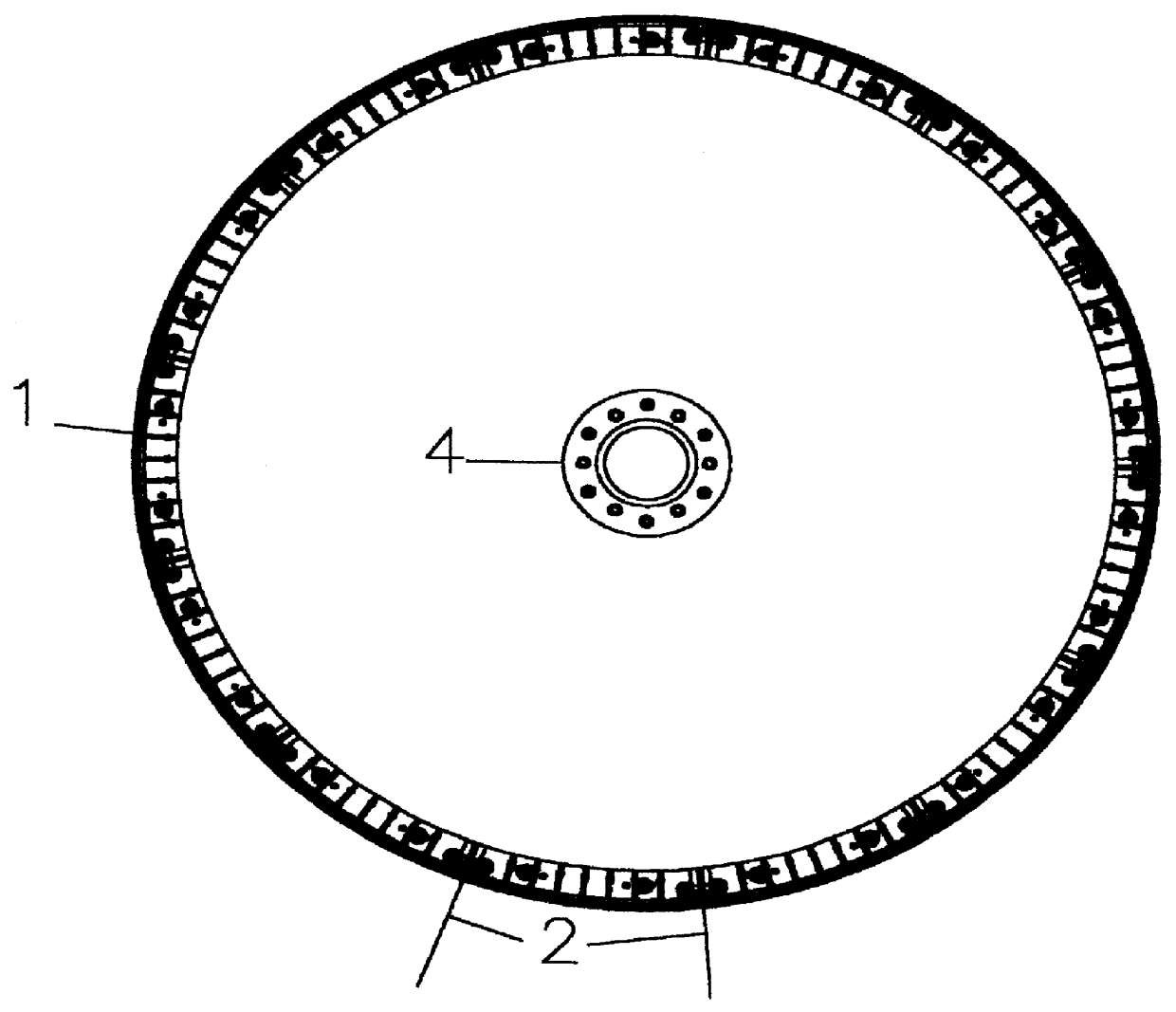
FIG. 1 is a side elevational view of apparatus employed in the practice of the invention and illustrates the assembly of the pad forming modules;

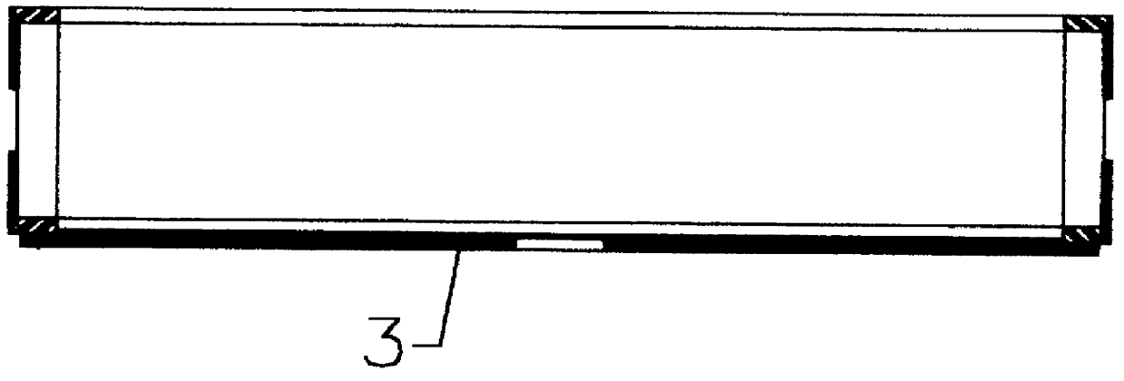
FIG. 2 is an end elevational view of the apparatus of FIG. 1;

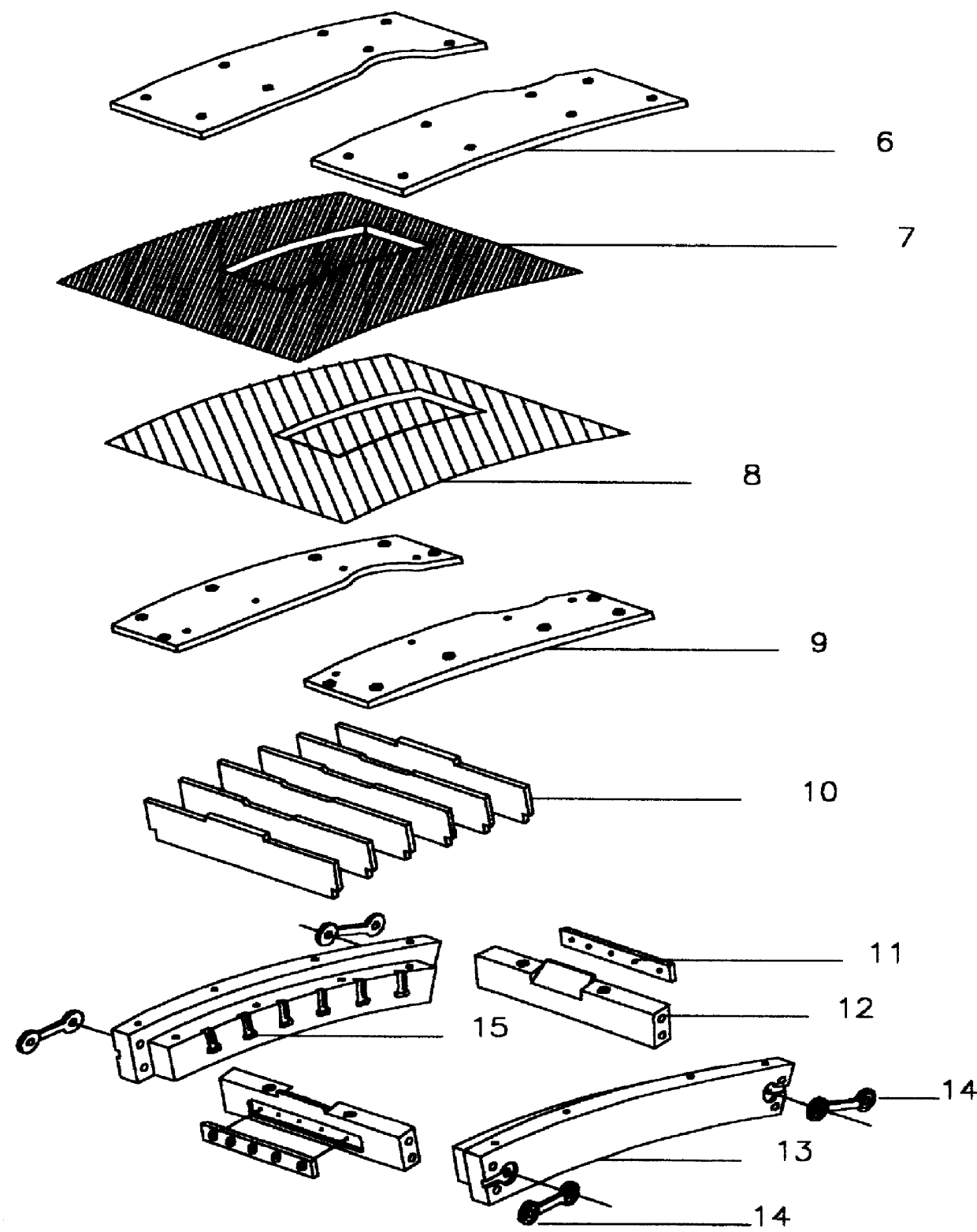
FIG. 3 shows the assembly of the components that comprise the modular pad forming assembly including the screen securing device;

FIG. 4 shows the off-set created between the top plates and sub-plates;

FIG. 5 shows the spacing of the cross directional guide airflow control louvers in accordance with the invention;

FIG. 6 shows the ends of the pockets and the joint created to smooth air flow during transition across the low pressure boundary.

FIG. 7 is a plan view of the concentricity stabilizer.

FIG. 8 shows a side view of the adjustable airflow control louver.

FIG. 9 shows a plan view of the adjustable airflow control louver having a linearly reduced profile,

FIG. 10 shows some...


PUM

PropertyMeasurementUnit
distanceaaaaaaaaaa
widthaaaaaaaaaa
angleaaaaaaaaaa

Abstract

The present invention provides an improved apparatus for forming a fibrous pad for absorbent products with improved density control. Fibers entrained in a high speed air flow are deposited onto the foraminous surface of a spaced, three-dimensional pad-forming pocket. The fine foraminous pad forming screen is supported on its periphery by two top plates, a coarse forming screen, two subplates and end rails which incorporate a device to hold the pad forming screen. A gas flow regulating system consisting of precisely placed cross directional fixed and adjustable airflow control louvers controls the air flow direction and reduces spill over and turbulence during the pad formation and especially during the transition of the forming pocket into and out of the air stream as the rotary former shell rotates through the filling position. Additional control of density and fiber placement is gained through the use of additional gas control innovations including a tapering the pocket ends such that the airflow is streamlined especially during pocket transition through forming sections.

Description

The present invention relates to an apparatus for forming fibrous pads used for absorbent applications such as disposable diapers and the like and more specifically to an apparatus employing a rotating drum containing a modular pad forming system wherein the density of the pad at any point, and especially at the circumferential extremes and across the pad width, is controlled by the use of any combination of specially spaced fixed and adjustable airflow control louvers and other air turbulence reducers located contiguous with or on the down stream side of the foraminous layer which describes the bottom of the forming pocket.BACKGROUND AND DESCRIPTION OF THE PRIOR ARTThis invention relates to an apparatus for forming fibrous pads, from cellulose or other fibers and including all forms of superabsorbent in any fluid conveyable form, for diapers or similar other absorbent products, and more particularly, to an apparatus employing modular foraminous forming pockets which when connected ...

Claims


Application Information

Patent Timeline
Patent Type & Authority Patents(United States)
IPC IPC(8): A61F13/15D01G37/00D04H1/70D04H1/00D01G99/00
CPCA61F13/15577A61F13/15658D01G99/00D04H1/70D04H1/005Y10T403/551Y10T403/553Y10T403/18D04H1/732
Inventor TONEY, JERRY L.TONEY, NATHAN E. E.NAJOUR, GERALDWARD, GREGORY F.
Owner TONEY JERRY L
Why Eureka
Try Eureka