Temperature control device for refrigerators

a temperature control device and refrigerator technology, applied in the direction of cooling fluid circulation, lighting and heating apparatus, domestic cooling apparatus, etc., can solve the problems of difficult limited maximum space available for storing foodstuffs, and difficult to achieve the access to the temperature control unit, etc., to achieve easy and comfortable handling, simple structure, and maximum utilization of the space available in the refrigerator

Inactive Publication Date: 2000-08-15
PANASONIC CORP
View PDF20 Cites 71 Cited by
  • Summary
  • Abstract
  • Description
  • Claims
  • Application Information

AI Technical Summary

Benefits of technology

Accordingly, the present invention has been devised with a view to substantially eliminating the above discussed problems which are inherent in the prior art temperature control devices used in the refrigerators and is intended to provide an improved temperature control unit which is effective to accom

Problems solved by technology

It has been found that the prior art temperature control units discussed above have the following problems.
Also, when a region of the refrigerating compartment RC between the refrigerator door RD and the rear wall where the temperature control unit is installed is filled with foodstuffs to be refrigerated, access to the temperature control unit is difficult to accomplish unless the foodstuffs are removed.
Moreover, considering that the temperature control box 22 is installed in a fashion protruding from the rear wall into the refrigerating compartment RC, the maximum space available for storing the foodstuffs tends to be limited.
This arrangement tends to bring about an increase in cost.
Also, the render information displayed through the display windows 26 is rather difficult to

Method used


Image

  • Temperature control device for refrigerators
  • Temperature control device for refrigerators
  • Temperature control device for refrigerators

Examples


first embodiment

(First Embodiment)

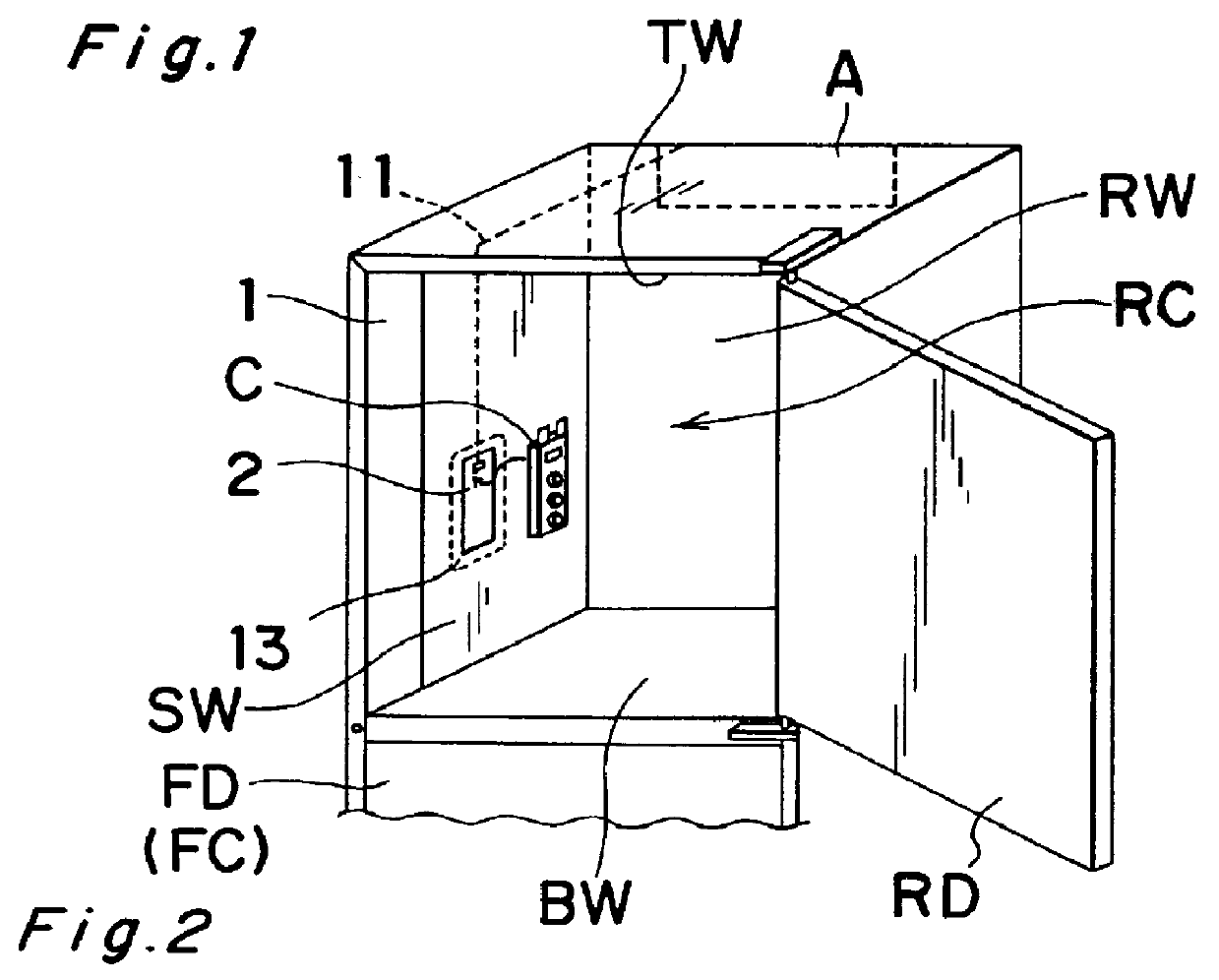
Referring now to FIGS. 1 and 2, the refrigerator comprises a rectangular box-like housing of a double-walled structure including outer and inner boxes with a heat insulating material 12 filled in a space between the outer and inner boxes. The refrigerator shown therein is of a type wherein the inner box is divided into a freezing compartment FC adapted to be opened or closed selectively by a freezer door FD and a refrigerating compartment RC located, for example, above the freezing compartment FC and adapted to be opened or closed selectively by a refrigerator door RD. The refrigerating compartment RC is delimited by a top wall TW, a bottom wall BW, a rear wall RW and opposite side walls SW, which form respective parts of the inner box 1 of the refrigerator housing. The-rear wall RW confronts the refrigerator door RD.

One of the opposite side walls SW of the inner box 1 is formed with a generally rectangular mounting hole 2 at a location adjacent the opening of the ...

second embodiment

(Second Embodiment)

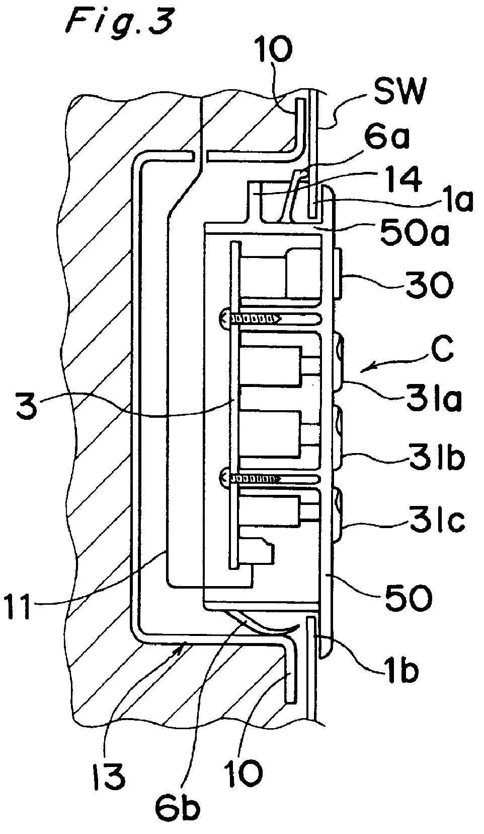
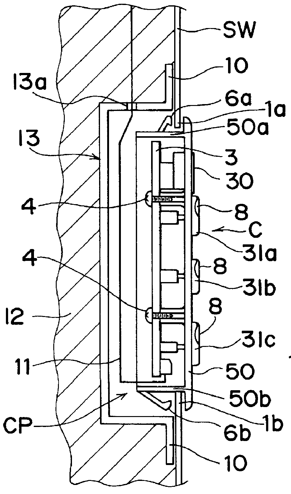
In the embodiment shown in FIGS. 3 and 4, the upper wall portion of the peripheral flange 50a is integrally formed with at least one transverse rib 14 positioned thereon in the same side of the upper tongues 6a in parallel to the front panel 50. The rib 14 protrudes upwardly therefrom a distance which smaller than the height of each upper tongue 6a as measured upwardly from the upper wall portion of the peripheral flange 50a. Also, the rib 14 extends in a direction that is widthwise of the console C and parallel to the plane of the front panel 50.

The transverse rib 14 serves as a means for avoiding or preventing any possible ingress of condensed droplets of condensed water into the space inside the peripheral flange 50a where the circuit carrier board 3 is disposed. More specifically, without the transverse rib 14, droplets of water formed by condensation of a vapor component and sticking to the side wall SW will enter in between the side wall SW and the upper end...

third embodiment

(Third Embodiment)

In this third embodiment of the present invention, an upright bottom wall of the console casing 13 defining the bottom of the console pocket CP is formed with a pair of vertically extending, juxtaposed upright ribs 15 which are spaced from each other a distance sufficient to accommodate the bundled electric lines forming the electric wiring 11. Also, the ribs 15 protrude toward the console C a distance that is sufficient to avoid the bundled electric lines from being bitten between the bottom wall of the console casing 13 and the console C when the latter is mounted in the console pocket CP. With the juxtaposed ribs 15, one or some of the bundled electric lines of the electric wiring 11 can be advantageously avoided from being broken during servicing or replacement of the console C.


PUM


Abstract

PCT No. PCT/JP97/02737 Sec. 371 Date Sep. 15, 1998 Sec. 102(e) Date Sep. 15, 1998 PCT Filed Aug. 6, 1997 PCT Pub. No. WO98/05911 PCT Pub. Date Feb. 12, 1998A temperature control device is provided in a refrigerator having at least one compartment (RC or FC) defined by top, bottom and opposite side walls (TW; BW; and SW), and a heat insulating material (12) exteriorly encircling the compartment. One of the side walls (SW) has a mounting hole (2) defined therein and a front surface thereof confronts the compartment (RC or FC). The device includes a box-like console (C), and a circuit carrier board (3) fixedly connected to a rear surface of the console (C). Electric wiring (11) extends outwardly from the circuit carrier board, and a display panel (30) is disposed on a front surface of the console (C). At least one manipulatable temperature control element (31a, 31b, 31c: PB, LED) is mounted on the console (C), and a hat-like console casing (13) having a peripheral flange (10) is fixedly secured to the side wall (SW) in alignment with the mounting hole (2). The peripheral flange (10) is held in abutment with a rear surface of the side wall (SW) so as to define a console pocket (CP). Also, a plurality of mounting elements (6a, 6b; 55) are engaged with an outer surface of the side wall (SW) around the mounting hole (2) for securing the console (C) to the side wall (SW). The console (C) is received in the console pocket (CP) with the electric wiring (11) accommodated within the console pocket (CP) and with the display panel (30) and the temperature control element confronting the compartment.

Description

The present invention generally relates to refrigerators and, more particularly, to a temperature control unit used in the refrigerator to control the temperature inside the refrigerator.A temperature control unit adapted for use in a refrigerator has been developed. By way of example, Japanese Patent Laid-open Publication No. 61-93375, published in 1986, discloses a temperature control unit installed in a rearmost wall of the refrigerating compartment such as shown in FIGS. 12 and 13, and the Japanese Patent Laid-open Publication No. 4-161779, published in 1992, discloses a temperature control unit installed outside the refrigerating compartment at a location between a freezer door and a refrigerator door such as shown in FIGS. 14 and 15.The refrigerator generally comprises a rectangular box-like housing of a double-walled structure including outer and inner boxes with a heat insulating material 12 filled in a space between the outer and inner boxes. The refrigerator shown in FIGS....

Claims


Application Information

Patent Timeline
IPC IPC(8): F25D29/00H01H37/00H01H37/04H01H37/06F25D23/00
CPCF25D29/005F25D2400/36F25D2400/40H01H37/043H01H37/06F25D29/00
Inventor ONAKA, TAKESHIMAEDA, KOUJIKISHINAKA, YUJIAOKI, TAKASHISASAKI, MASATOSHI
Owner PANASONIC CORP
Why Eureka
Try Eureka