Hologram device and method for producing the same

a holographic device and a technology for producing holograms, applied in the field of holographic devices and holographic methods for producing holograms, can solve the problems of inability to obtain the desired quality of holograms, complex system, and defective prior art methods in fig. 53

Inactive Publication Date: 2000-08-29
DENSO CORP
View PDF18 Cites 18 Cited by
  • Summary
  • Abstract
  • Description
  • Claims
  • Application Information

AI Technical Summary

Problems solved by technology

However, these methods in the prior arts are defective in that three laser devices for laser beams of red, green and blue colors are necessary, which makes the system complicated.
Furthermore, the prior art method in FIG. 53 is also defective in that a desired quality of a hologram cannot be obtained when a large size of a hologram is needed due to a limitation in the size of the diffusing body.
A use of a diffusing body of such an increased size is actually impossible due to a limitation in a designing of an optical system.
Namely, a limitation of the size of a light diffusing body makes it difficult to obtain a hologram screen of an increased size.
This makes the intensity of the laser beam to be reduced per unit area of the photo-sensitive member 120, which prolongs the exposure time, which is much longer than a period in which interference fringes stay in a stable condition on the photo-sensitive member 120, which makes the production of a hologram of an increased size very difficult.
On the other hand, the time which is allowed for a production of a hologram is usually as short as about 10 minutes, which is much shorter than the above mentioned desired exposure time, which makes it very difficult to produce a hologram.

Method used


Image

  • Hologram device and method for producing the same
  • Hologram device and method for producing the same
  • Hologram device and method for producing the same

Examples


first embodiment

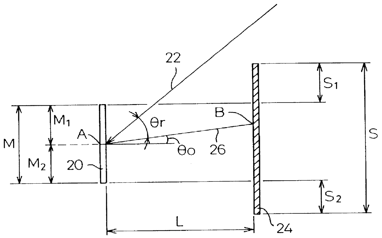
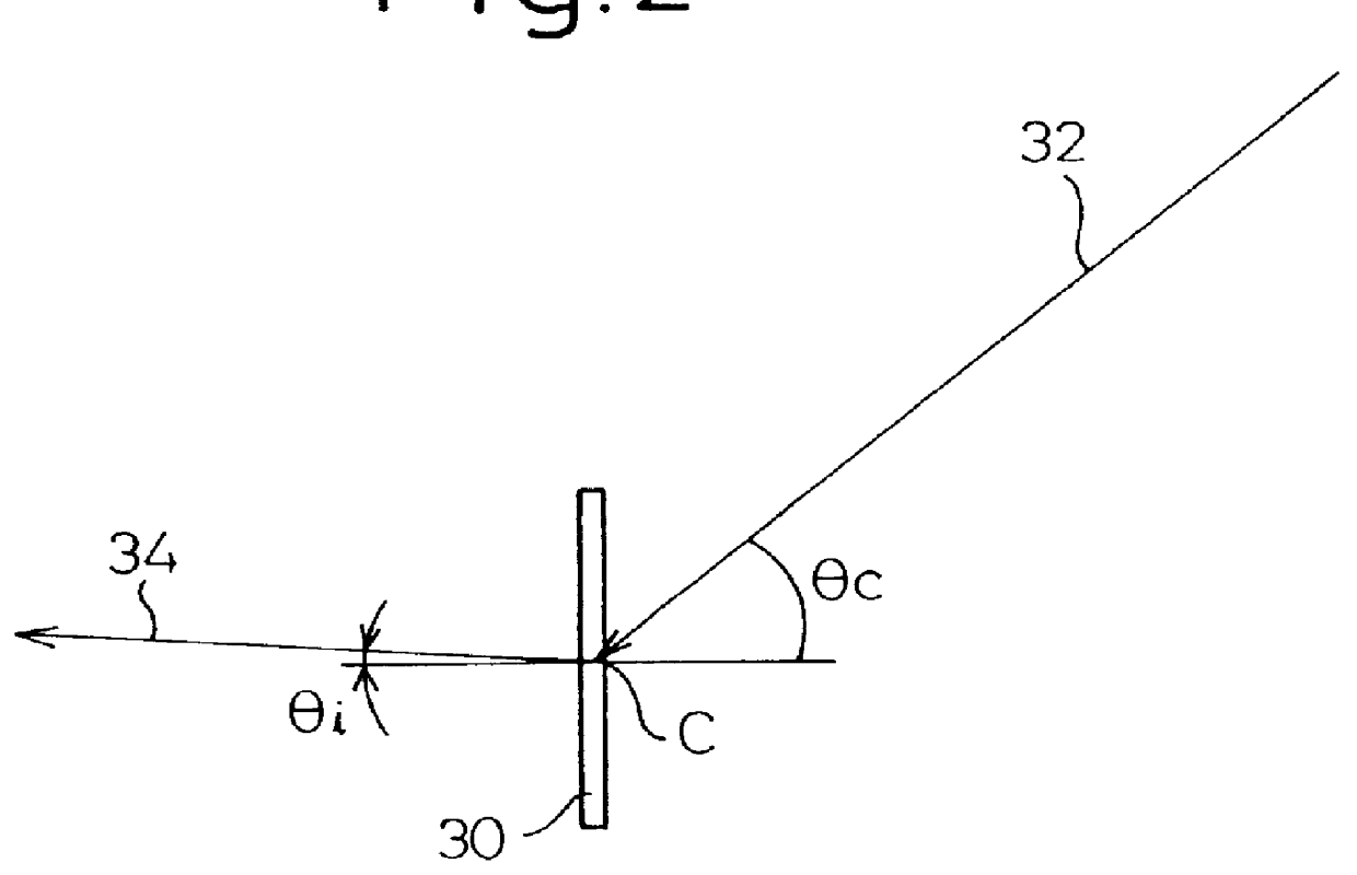
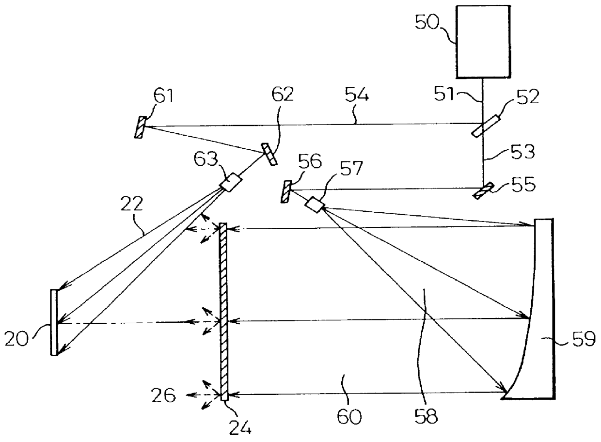
Now, embodiments of the present invention overcoming the above mentioned difficulty will be explained. FIG. 4 shows an optical system for an exposure according to present invention, which includes a laser beam generator 50 for generation of a laser beam 51 which is directed to the beam splitter 52, whereat the laser beam 51 is divided to two beams, a first beam 53 and a second beam 54. The first beam 53 is directed via a first mirror 55 and a second mirror 56 to a first object lens 57 by which an expanded beam 58 is created. This expanded beam 58 is directed to an off-center parabolic surface concave mirror 59 so that a horizontal parallel beam 60 is obtained, which passes through a light diffusing body 24. The passage of the parallel beam through the light diffusing body 24 causes an object light 26 to be generated, which illuminates a photo-sensitive member 20.

The other laser beam 54 is directed, via a third mirror 61 and a fourth mirror 62, to a second object lens 63, where a div...

second embodiment

According to the present invention, it is necessary that, in order to obtain an integrated assembly 30, the holograms 310 and 320 are arranged carefully so that a gap is not created in the seam between the holograms 310 and 320. Now, a method according to present invention for arranging holograms without generating any gap between the holograms 310 and 320, which are adjacent with each other, will be explained, with reference to FIGS. 14a and 14b to FIGS. 16a and 16b.

In the first step of the process, the hologram 310 as produced by the method as explained with reference to FIGS. 1 to 13 is stripped from the glass plate 74 as shown in FIGS. 14a and 14b. Similarly, the hologram 320 is also stripped from the glass plate 75. Then, the hologram sections 310 and 320 are arranged so that side edges of the hologram sections, which are adjacent with each other, are slightly overlapped as shown, in particular, in FIG. 15b. Then, a cut is made along seam lines A--A and B--B located along the o...

third embodiment

According to the embodiment, an optimum arrangement of the hologram device 30 obtained by the method according to present invention is determined by tests. Namely, evaluations of the reliability, the invisibility of an end of the hologram device 30, and the workability were done.

In this embodiment, the base plate 73 is made from a polyethylene terephtharate, and the adhesive layer 72 is made from ionopolymer.

The hot laminate was done by a hot laminator having hot rolls 90 and 91 in FIG. 9 having a diameter of 150 mm and an air cylinder for pressing having a diameter of 63 mm. The temperature of the roll is in a range between 100 to 130.degree. C. and the pressure at the pressure cylinder is in a range between 1 to 4.5 kg / cm.sup.2.

The reliability was evaluated by a degree of change in a wave length, a degree of change in an efficiency and a degree of change in a half band width.

The non-visibility of the end of the hologram element was evaluated by a sensory test as to a screen of an ...


PUM


Abstract

A hologram of an increased size using a single color laser, capable of executing a full color regeneration in a desired view angle and a method for producing the hologram. A plurality of photo-sensitive members are independently exposed to obtain respective holograms, which are connected by using an adhesive layer 80 constructing a connecting means, in order to obtain an integrated hologram expanded in two-dimensional direction. The holograms are obtained by an interference of a reference light 22 and an object light passed through a light diffusing body 24 in order to cause the light diffusing body 24 to be recorded on the photo-sensitive member. The size of the light diffusing body 24 is such that the spectral characteristic of the diffused light from the hologram can attain a desired efficiency at least over the entire wavelength range of the visible light.

Description

1. Field of the InventionThe present invention relates to a hologram device and a method for producing a hologram and, in particular, to a screen hologram where a hologram is used for a screen and a method for producing such a screen hologram.2. Description of Related ArtA screen hologram is known in the prior art. See, for example, Japanese Examined Patent Publication No. 52-12568. In such a screen hologram, a content of a display device is imaged on a transparent screen created under a principle of a hologram, so that a viewer can see the image, while allowing the viewer to see the background via the transparent screen. When the display device is not in use, the screen hologram acts only as a transparent plate.Such a screen hologram is used, for example, for displaying a content such as an advertisement on a show window in a department store or an underground shopping mall and for displaying a necessary information at counter for a customer or a patient in a bank or hospital, whil...

Claims


Application Information

Patent Timeline
IPC IPC(8): G03H1/26G03H1/02G02B5/32
CPCG02B5/0252G02B5/32G03H1/26G03H1/0486G03H2001/0473G03H2001/2236G03H2001/306G03H2210/20G03H2223/14G03H2250/12G03H2250/32G03H2250/39
Inventor HATTORI, HIDEKAZUTAKADA, KENICHIRONISHII, KATSUYOSHIMATSUMOTO, TOORUKANDA, TOMOYUKI
Owner DENSO CORP
Why Eureka
Try Eureka