Sequential color display device including light shading means

a display device and color technology, applied in the field of display devices, can solve the problems of increased temperature of the color wheel case itself, increased cost, and difficulty in cooling the color wheel and the motor in the case, and achieve the effect of accurate detection

Inactive Publication Date: 2006-02-28
PANASONIC CORP
View PDF25 Cites 28 Cited by
  • Summary
  • Abstract
  • Description
  • Claims
  • Application Information

AI Technical Summary

Benefits of technology

[0031]It is an object of the present invention to provide a color wheel assembly comprising a color wheel and a motor for rotating the color wheel, in which the position of the color wheel can be accurately detected even at high-speed rotation or at elevated temperatures, and a field sequential color display device using this color wheel assembly.

Problems solved by technology

Further, when the color wheel is housed in the case, the temperature of the color wheel case itself is increased due to heat radiated from the lamp or absorption of unnecessary light, whereby it becomes difficult to cool the color wheel and the motor in the case.
These steps both should be carried out accurately, which leads to increases in costs.
At this time, the photo-sensor 374 interferes with the air current, leading to noises.
Further, to allow the photo-sensor 374 to read the index mark, the hub area through which light does not directly pass is required, and this presents a problem in minimizing the diameter of the color wheel or miniaturizing.
Even when the color wheel is housed in the case, since the rotation of the color wheel creates wind pressure, and air frequently flows into or out of the gap of the case, the filters similarly become dirty with time.
Especially when the color wheel is housed in the case, it is necessary to provide an opening for incoming or outgoing light, and the incoming / outgoing air into / from the opening causes the dust to be caught in the case.
When the color wheel which is constituted by thin glass filters rotates at a high speed and cuts through the air, a whistling sounds occur, and it becomes the source of large noise, together with the electromagnetic sounds of the motor.
Especially when the color wheel is housed in the case, the air current is generated by the wind pressure resulting from the rotation of the color wheel from an opening which is provided for incoming or outgoing light, and the incoming / outgoing air into / from the opening causes noise.

Method used


Image

  • Sequential color display device including light shading means
  • Sequential color display device including light shading means
  • Sequential color display device including light shading means

Examples


embodiment 1

[Embodiment 1]

[0122]Hereinafter, a color wheel assembly according to the first embodiment of the present invention will be described with reference to FIGS. 1 and 2.

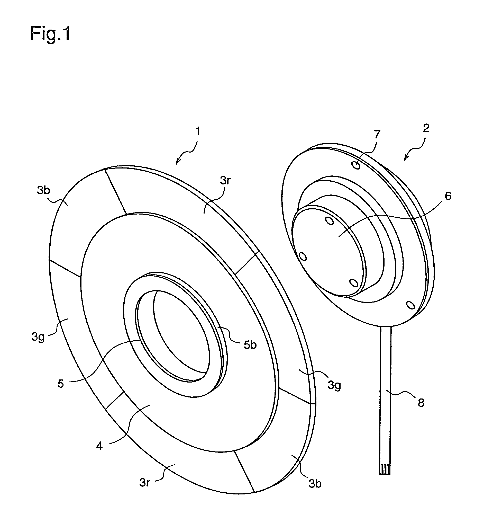
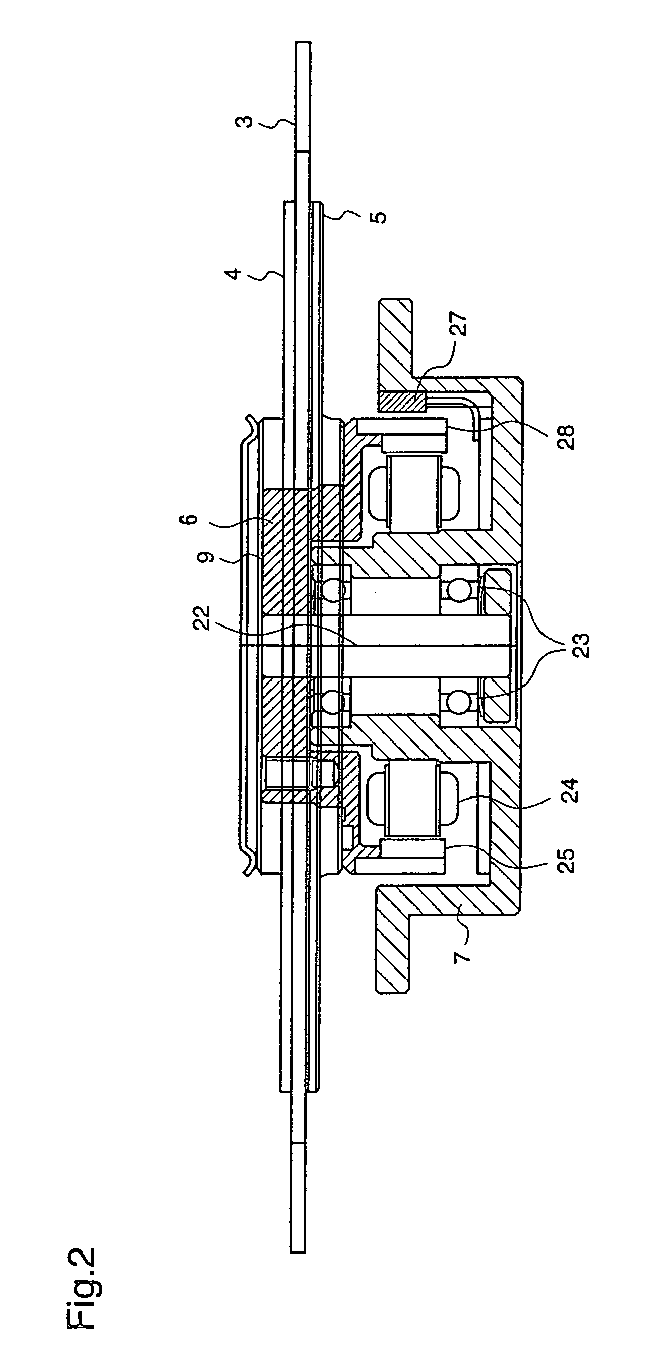
[0123]FIG. 1 is a diagram schematically illustrating an example of the color wheel assembly of the first embodiment. As shown in FIG. 1, the color wheel assembly of the first embodiment is constituted by a color wheel 1 and a motor 2.

[0124]The color wheel 1 comprises red (R), green (G) and blue (B) color filters 3r, 3g and 3b, which are sandwiched and fixed by hubs 4 and 5 on opposing sides.

[0125]Each of the color filters 3r, 3g, and 3b is a glass pane of a thickness of 1 mm, and its outside shape is processed approximately in the form of a fan having a 60°-interior angle. An optical thin film is coated on these color filters 3r, 3g and 3b, respectively, on the surface of the glass pane, such that transmitted white light is modulated into light of R, G and B, respectively, and two filters for each color, i.e., 6 filters ...

embodiment 2

[Embodiment 2]

[0139]When a color wheel assembly according to the present invention is to be used in a field sequential color display device, the positional relationship between the color wheel and the motor is significantly important. A pulse signal is generated from the motor as in the above-mentioned first embodiment, then the pulse signal is compared with a reference signal to control the speed and phase of the motor, and the color switching of the filters of the color wheel in the field sequential color display device is made to be driven according to the color of light which is modulated by the SLM. Accordingly, in order to output the pulse signal at a predetermined color switching, the mounting of the color wheel and the motor should be univocally decided. Besides, it is preferable that their initially adjusted states should be maintained.

[0140]Hereinafter, a color wheel assembly according to the second embodiment is described with reference to FIG. 3.

[0141]FIG. 3 is a diagram...

embodiment 3

[Embodiment 3]

[0146]Hereinafter, a color wheel assembly according to the third embodiment of the present invention will be described with reference to FIG. 4.

[0147]FIG. 4 is a diagram schematically illustrating an example of the color wheel assembly of the third embodiment. The color wheel assembly of the third embodiment is different from the color wheel assembly of the first embodiment only in that it positions a color wheel and a motor. The same reference numerals as those in the first embodiment denote the same or corresponding elements.

[0148]The color wheel assembly of the third embodiment is constituted by a color wheel 41 and a motor 42.

[0149]The color wheel 41 comprises red (R), green (G) and blue (B) color filters 3r, 3g and 3b, which are sandwiched and fixed by hubs 44 and 45 on opposing sides. Further, keyways 46 and 48 are provided at the periphery of an opening of the hub 44 of the color wheel 41, connected with the motor, and a rotor part 47 of the motor 42, respective...


PUM


Abstract

A projection display device includes a condensing unit and a shading unit. The condensing unit condenses light emitted from a light source to form a condensed spot on a color wheel. The shading unit, when a size of the condensed spot on the color wheel has increased due to an increase in light emission of the light source, shades a portion of the light passing through the color wheel corresponding to the increased size.

Description

[0001]This application is a divisional of Ser. No. 09 / 864,333, filed May 25, 2001 now U.S. Pat. No. 6,755,554.FIELD OF THE INVENTION[0002]The present invention relates to a display device using a spatial light modulator (SLM) or light valve which works at a considerably high speed and, more particularly, to a color wheel assembly and a field sequential color display device using the same, a color wheel unit and a field sequential color display device using the same, and a field sequential color display device, to display colors in a time-multiplexing and color sequential manner.BACKGROUND OF THE INVENTION[0003]In recent years, attention has been increasingly focused on large screen displays such as home theaters and presentations, and projectors are recently being commercialized which use a small reflective light valve of a liquid crystal on silicon (hereinafter, referred to as LCOS) in which a switching element, a reflection electrode or the like is formed on a silicon substrate or...

Claims


Application Information

Patent Timeline
Patent Type & Authority Patents(United States)
IPC IPC(8): F21V11/16F21S10/00G02B7/00H04N5/74H04N9/31
CPCF21S10/007G02B26/008H04N9/3197H04N9/3114H04N9/3144G02B7/006H04N9/3141H04N5/7441
Inventor OHMAE, HIDEKIWADA, MITSUHIROTANABE, KAZUNORIARUGA, SHIGERUSAKAGUCHI, HIROKAZUSHIMOSE, HISATOSHI
Owner PANASONIC CORP
Why Eureka
Try Eureka