Suture ring for heart valve prosthesis

a technology for suture rings and heart valves, applied in the field of suture rings for heart valve prostheses, can solve the problems of difficult insertion of leaflets, significant percentage of permanent damage, and damage to both subassemblies

Inactive Publication Date: 2000-09-05
REPUBLIC MEDICAL PRODS
View PDF4 Cites 52 Cited by
  • Summary
  • Abstract
  • Description
  • Claims
  • Application Information

AI Technical Summary

Problems solved by technology

If the orifice ring is too stiff, a significant percentage may be permanently damaged during the insertion process.
It is possible, therefore, to damage the subassembly both during and after implantation.
This makes the insertion of the leaflets more difficult and reduces the internal diameter of the orifice ring, both of which are undesirable.
The disadvantage to this method of constraint is that it requires the orifice ring to be thicker than it would be if the constraint were to be applied over a larger portion of the external diameter of the orifice ring.
Increasing the thickness of the orifice ring results in a decrease in the inside diameter of the orifice ring, which is an undesirable effect.
The disadvantage to this method of constraint is that it too r

Method used


Image

  • Suture ring for heart valve prosthesis
  • Suture ring for heart valve prosthesis
  • Suture ring for heart valve prosthesis

Examples


Embodiment Construction

The following description is of the best mode presently contemplated for practicing the invention. This description is not to be taken in a limiting sense, but is made for the purpose of describing the general principles of the invention. The scope of the invention should be determined with reference to the claims. The preferred embodiment of the present invention will now be described with reference to the accompanying drawings. In the drawings, like numerals will be used to designate like parts throughout.

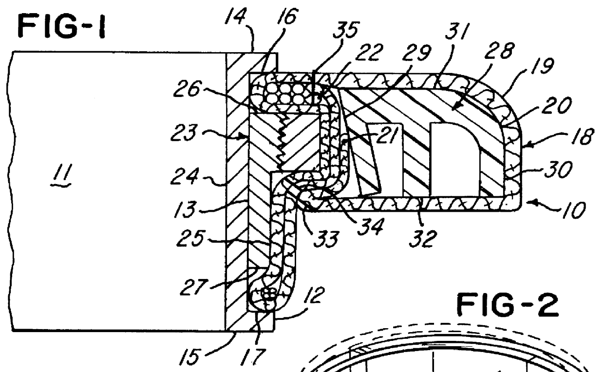
FIG. 1 depicts a cross-sectional view of the suture ring 10, attached to the orifice ring 11. The orifice ring 11 may house leaflets as disclosed in U.S. Pat. No. 4,950,287-Reif dated Nov. 12, 1991. The orifice ring has an outer circumferential surface 12 with a substantial annular groove 13. The orifice ring 11 has a first axial end 14 and a second axial end 15. Flanged surfaces 16 and 17 are formed at the intersection of the outer circumferential surface 12 and the annular groo...


PUM


Abstract

A heart valve stiffening ring of this disclosure includes a split ring that allows assembly over a channel-shaped heart-valve-orifice-forming angular heart valve body, with the split ring having an outer peripheral tapered thread, which allows adjustment of pressure between the split ring and the orifice-forming annular body. A solid ring or nut has complementary tapered threads to mate with the outer peripheral tapered thread of the split ring and is adjustable for tightening of interfit thereof to bring about correct pressure for desired tightening effect with a moment of inertia in bending of the outer channel to make the orifice stronger so that orifice outer diameter thereof can be a maximum value. The angle of taper is substantially 3 degrees with respect to the center line. This heart valve stiffening ring can be employed in place of a heart valve locking ring of U.S. Design Pat. No. 376,206-Reif issued Dec. 3, 1996. Improvement of the present design includes a major feature or crux that the split ring and solid ring or nut both have complementary threads that fit together and using the flanges of the channel configuration used therewith.

Description

1. Field of the InventionThe present invention relates to a heart valve prostheses, and more particularly to suture rings for supporting heart valve prostheses.2. Description of the Prior ArtThere are two types of heart valve prostheses, biological and mechanical. The medical indications for heart valve replacement are the same for both types. Examples include rheumatic heart disease, congenital anomalies, and myocardial infarction.Unidirectional flow is the primary function of the heart valve prostheses. This is usually accomplished by fashioning rigid or flexible leaflets, free to articulate within certain limitations, within an annular shaped frame, frequently referred to as an orifice ring. The restrained motion of these leaflets causes the flow to be essentially unidirectional, mimicking the natural function of the native heart valves.While the features of the present invention can be used in either biological or mechanical valves, for purposes of facilitating explanation there...

Claims


Application Information

Patent Timeline
IPC IPC(8): A61F2/24
CPCA61F2/2409
Inventor REIF, THOMAS H.
Owner REPUBLIC MEDICAL PRODS
Why Eureka
Try Eureka