Double-sided reflector films

a double-sided reflector and film technology, applied in the field of double-sided reflector films, can solve the problems of vexing problems, plastic substrates tend to degrade or discolor prematurely, etc., and achieve the effects of stable, durable double-sided reflective, durable and stable commercial applications, and long-lasting

Inactive Publication Date: 2000-09-12
SOUTHWALL TECH INC
View PDF11 Cites 3 Cited by
  • Summary
  • Abstract
  • Description
  • Claims
  • Application Information

AI Technical Summary

Benefits of technology

In accord with our invention we have found that a particular regimen of preglow treatment of the plastic substrate leads to stable, durable double-sided reflective films. More particularly, we have discovered that if the nonslip side of the plastic film is preglowed and the slip side is not preglowed prior to depositing their respective reflective coatings, the resulting product is durable and more stable and acceptable for commercial application.
Thus in one embodiment this invention provides a method for producing a reflective composite film. This method applies to plastic film having a slip side and a nonslip side. It involves applying, by sputtering, a reflective layer to each side of the plastic film but preglowing only the nonslip side of the film. This method yields a coated film product which is significantly and unexpectedly more durable and long-lived than similar double-sided products made with plastic films preglowed on both sides.

Problems solved by technology

This has not found acceptance typically because the plastic substrate tends to degrade or discolor prematurely when this is done.
This has been a vexing problem since double-sided materials do possess certain theoretical performance advantages.

Method used


Image

  • Double-sided reflector films
  • Double-sided reflector films
  • Double-sided reflector films

Examples


example 1

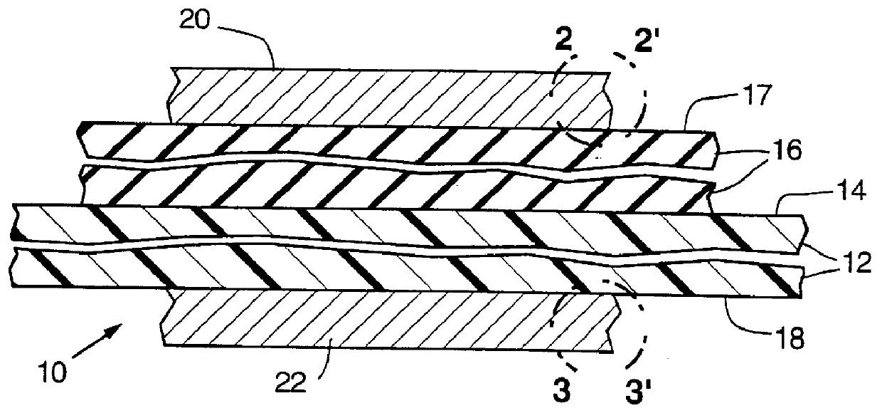
A film product of the invention was prepared as follows. A supply of 3 mil thick poly(ethyleneterephthalate) was obtained. This material, a commercial material marketed by Teijin, had a slip coating of polyester and acrylate on one side. The other side was uncoated.

This material was converted into a double sided reflector film as follows. It was loaded into a laboratory scale moving web sputtering unit of the general type shown in FIG. 4.

This preparation involved a two pass coating operation with a three cathode dielectric / metal / dielectric ("DMD") stack being deposited on both sides of the substrate. In the first pass, the nonslip side was coated using a dc preglow. In the second pass, the slip side was coated with the DMD coating using no dc preglow.

Pass I Deposition conditions:

Linespeed: 7.74 mm / sec

Substrate Side: nonslip

Approximate stack design: 410 .ANG. In.sub.2 O.sub.3 / 90 .ANG. Ag / 410 .ANG. In.sub.2 O.sub.3

Preglow: 1500 V @ 32.5 mA, 13.6 sccm of air, pressure 10.times.10.sup....

example 2

The QUV a Yellowing Test

To determine the rate at which PET based reflector samples yellow when exposed to solar radiation, an accelerated test was done. In this test sample films were suspended into sealed air filled insulated glass units ("IGUs"). The igu's are fabricated using low iron glass (i.e. UV transmissive) on the exposed side of the unit. As described in ASTM G53-84, samples were exposed to a UVA-351 bulb through 3 mm low iron glass supplied by Schott. The UV exposure was applied at a 100% duty cycle and a one sun intensity. During the exposure, the samples were held at 60.degree. C. and a relative humidity of 40%.

The results of this exposure for three different samples (Example 1, A and B) is given in FIG. 5.

Sample B is a double sided reflector on PET. In single sided reflectors in the past the nonslip side of PET is coated with a reflective layer using a dc preglow to enhance the adhesion of the coating to PET. When the reflective coating is applied to the slip side usin...


PUM

PropertyMeasurementUnit
thicknessaaaaaaaaaa
thicknessaaaaaaaaaa
transparentaaaaaaaaaa

Abstract

Durable-long lived plastic films carrying sputter-deposited metal layers such as reflective metal layers on both sides are disclosed. The slip side of the plastic film is not preglowed. The nonslip side is preglowed. This combination of glowing and not preglowing leads to the desired long life.

Description

This invention relates to plastic films which carry metal-containing reflector layers on both sides. More particularly, it concerns such double metal layer carrying plastic films which are light transmissive and which exhibit long-term stability.DESCRIPTION OF BACKGROUND MATERIALSIt is common practice to employ partially reflective--partially transmissive metal layer bearing films in glazing structures. These films may be applied to the surface of glass window glazing materials. They may be laminated into glazing structures. They may be suspended alone or in combination with other sheets of glazing. These products typically have a plastic film substrate which carries the reflector metal layer adherent to it. As will be described in more detail, plastic films are often marketed with a coating, known in the art as a slip coating, on one side to facilitate handling during production and fabrication. The side of the film having the slip coating is called (not unexpectedly) the "slip" si...

Claims


Application Information

Patent Timeline
Patent Type & Authority Patents(United States)
IPC IPC(8): C23C14/56C23C14/20C23C14/02B32B15/08B32B27/36C23C14/34G02B1/10
CPCC23C14/022C23C14/205C23C14/562G02B5/0858Y10T428/12569Y10T428/12889Y10T428/12542Y10T428/24355Y10T428/12896Y10T428/31678Y10T428/31681Y10T428/31786C23C14/34
Inventor WOODARD, F. EUGENEPASS, THOMASLARSEN, TED L.
Owner SOUTHWALL TECH INC
Why Eureka
Try Eureka