Multi-point OFDM/DMT digital communications system including remote service unit with improved transmitter architecture

a digital communication system and remote service technology, applied in phase-modulated carrier systems, frequency-division multiplexes, polarisation/directional diversity, etc., can solve the problems of increasing the use of cable telephony systems, increasing the bandwidth allocated to cable telephony systems, and affecting the reliability of the system. the secondary site of the system described in the report, so as to achieve the effect of improving the transmitter architectur

Inactive Publication Date: 2000-09-12
TELLABS OPERATIONS
View PDF16 Cites 45 Cited by
  • Summary
  • Abstract
  • Description
  • Claims
  • Application Information

AI Technical Summary

Benefits of technology

A multi-point communications system is set forth herein. The communications system includes a receiver and transmitter disposed at a primary site for communication with a plurality of remote service units disposed at respective secondary sites. The receiver of the primary site receives OFDM/DMT signals over a number of transmission bins. A transmitter at the remote service unit includes an improved transmitter architecture. The transmitter comprises a first circuit for converting a signal into a first serial digital data stream and a s...

Problems solved by technology

As the number of cable telephony subscribers increases over time, the increased use will strain the limited bandwidth allocated to the cable telephony system.
It is often impractical to increase the bandwidth allocated to the cable telephony system given the competition between services for the total bandwidth assigned to the cable service provider.
The transmitters ...

Method used


Image

  • Multi-point OFDM/DMT digital communications system including remote service unit with improved transmitter architecture
  • Multi-point OFDM/DMT digital communications system including remote service unit with improved transmitter architecture
  • Multi-point OFDM/DMT digital communications system including remote service unit with improved transmitter architecture

Examples


Embodiment Construction

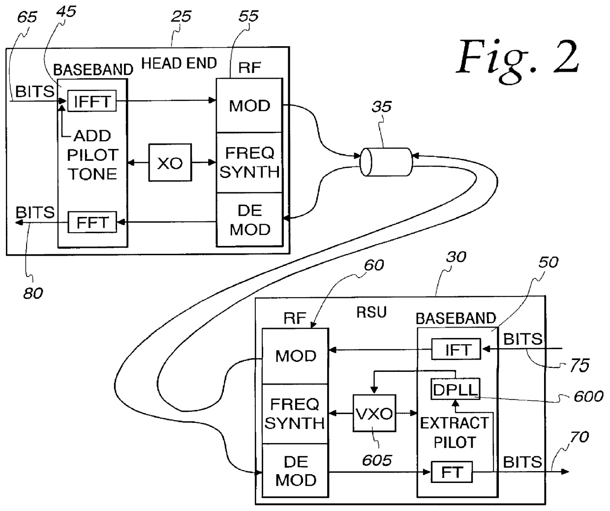
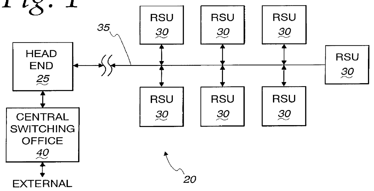
FIG. 1 is a block diagram of a multi-point communications system which may use a remote service unit having the improved receiver and transmitter architectures disclosed herein. As illustrated, the communications system, shown generally at 20 includes a head end unit (HE) 25 disposed at a primary site. The head end unit communicates with a plurality of remote service units (RSUs) 30 respectively disposed at a plurality of secondary sites, over a transmission medium 35 such as a coaxial cable.

The digital communications system 20 may, for example, be a cable telephony system. In such an application, the head end unit 25 is disposed at a cable television transmission facility while the remote service units 30 are disposed at individual customer locations, such as individual customer homes. The transmission medium 35 would be the new or existing transmission cable used to transmit the cable television services. The head end unit 25 in a cable telephony network is responsible for communi...


PUM


Abstract

A multi-point communications system is set forth herein. The communications system includes a receiver and transmitter disposed at a primary site for communication with a plurality of remote service units disposed at respective secondary sites. The receiver of the primary site receives OFDM/DMT signals over a number of transmission bins. A transmitter at the remote service unit includes an improved transmitter architecture. The transmitter comprises a first circuit for converting a signal into a first serial digital data stream and a second circuit for generating a second serial digital data stream from the first serial digital data stream of the first means. The second serial digital data stream is a digital representation of an OFDM/DMT signal that is to be transmitted to the receiver of the primary site and is generated from the first serial digital data stream through a modulated direct digital synthesis thereof. A third circuit is used to convert the second serial digital data stream into an analog OFDM/DMT signal for transmission to the receiver of the primary site.

Description

BACKGROUND OF THE INVENTIONThe present invention is directed to a remote service unit for use in an OFDM / DMT digital communications system. More particularly, the present invention is directed to an improved transmitter architecture for use in aremote service unit of a multi-point, OFDM / DMT digital communications system.Multi-point communications systems having a primary site that is coupled for communication with a plurality of secondary sites are known. One such communications system type is a cable telephony system. Cable telephony systems transmit and receive telephone call communications over the same cable transmission media as used to receive cable television signals and other cable services.One cable telephony system currently deployed and in commercial use is the Cablespan 2300 system available from Tellabs, Inc. The Cablespan 2300 system uses a head end unit that includes a primary transmitter and primary receiver disposed at a primary site. The head end unit transmits and...

Claims


Application Information

Patent Timeline
IPC IPC(8): H04L27/26H04L5/02H04L5/14H04B1/66H04B7/10H04J1/00H04J11/00
CPCH04L5/023H04L5/1453H04L27/20H04L27/2602H04L27/2628H04L27/2647H04L27/2662H04L27/2657
Inventor MARCHOK, DANIEL J.YOUNCE, RICHARD C.MELSA, PETER J. W.
Owner TELLABS OPERATIONS
Why Eureka
Try Eureka