Laser therapy system and method of cutting and vaporizing a tissue body

a tissue body and laser therapy technology, applied in the field of new laser therapy systems and methods, can solve the problems of surgeons having difficulty viewing, unable to direct laser energy from the distal end of the fiber optic to the tissue body, and still remains a significant post-operative morbidity and patient trauma

Inactive Publication Date: 2000-10-03
HAJJAR JOHN H
View PDF2 Cites 17 Cited by
  • Summary
  • Abstract
  • Description
  • Claims
  • Application Information

AI Technical Summary

Benefits of technology

After reading and understanding the foregoing detailed description of an inventive laser therapy system and method of cutting and vaporizing a tissue body in accordance with preferred embodiments of the invention, it will be appreciated that several distinct advantages of the subject laser therapy system and method of cutting and vaporizing a tissue body are obtained.Without attempting to set forth all of the desirable features of the instant laser therapy system and method of cutting and vaporizing a tissue body, at least some of the major advantages include providing a catheter 20 having a brush assembly 22 secured to a distal end portion 24 of the catheter 20 and a fiber optic 12 which is received in the lumen of the catheter 20. The catheter 20 with inserted fiber optic 12 is directed to a treatment site, such as a bladder and adjacent to the prostate. The fiber optic 12 is extended beyond a distal end 25 of the catheter 20 and a energy is supplied to the fiber using a standard surgical laser system where the body tissue is cut and vaporized by a beam of energy projected from the fiber 14.The use of the catheter brush assembly 22, 32 of the present invention allows for an effective and efficient technique for cleaning the distal end 19 of a fiber optic. The surgeon is not required to remove the fiber optic from the treatment site during a surgical procedure thereby reducing procedure time and reducing patient trauma. The fiber optic is simply retracted into the catheter lumen through the brush assembly 22, 32 and the distal end of the fiber is wiped free of fragments and debris. Moreover, the surgeon can maintain eye contact with the treatment site throughout the procedure without the need for turning away to wipe the removed fiber. This will insure localized cutting and vaporization without the need for relocating the subject tissue body. Furthermore, a surgeon of any skill can operate the laser therapy system of the present invention to obtain desirable results and can utilize standard laser equipment and viewing equipment.In describing the invention, reference has been made to a preferred embodiment and illustrative advantages of the invention. Those skilled in the art, however, and familiar with the instant disclosure of the subject invention, may recognize additions, deletions, modifications, substitutions and other changes which fall within the purview of the subject invention.

Problems solved by technology

Although this technique has proven successful and represents a major advance over open surgical prostatic enucleation, there still remains a significant post-operative morbidity and patient trauma associated with this procedure.
One of the problems associated with laser therapy has been the difficulty of directing the laser energy from the distal end of the fiber optic to the tissue body.
This is because the surgeon would have difficulties viewing the procedure when fragments and debris engulfed the distal portion of the fiber and blocked viewing through a conventional cystoscope.
If the fragments and debris are not removed, the laser energy is not permitted to effectively cut and vaporize remaining tissue body.
Moreover, if the fragments are allowed to remain on the outer surface of the ADD.TM., an insulation effect is generated and a large heat build up will occur which melts the glass window and degrades the fiber.
However, such fragment and debris build up on the fiber system is disadvantageous in all laser therapy procedures whether the laser energy is side or end directed.

Method used


Image

  • Laser therapy system and method of cutting and vaporizing a tissue body
  • Laser therapy system and method of cutting and vaporizing a tissue body
  • Laser therapy system and method of cutting and vaporizing a tissue body

Examples


Embodiment Construction

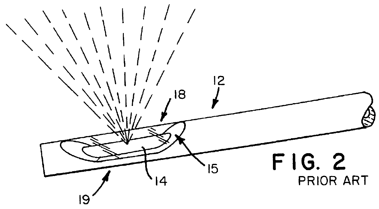
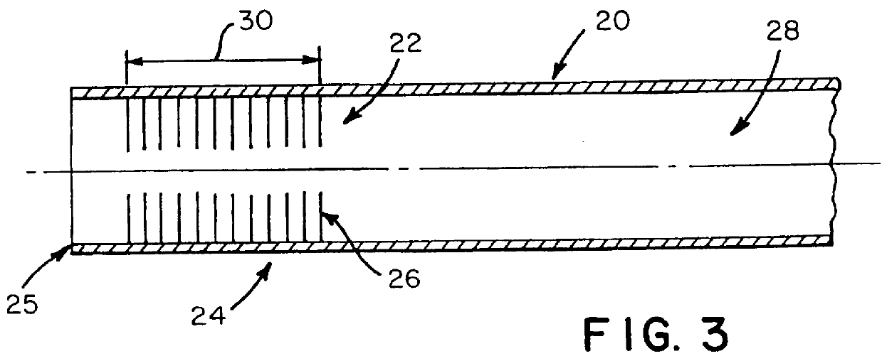
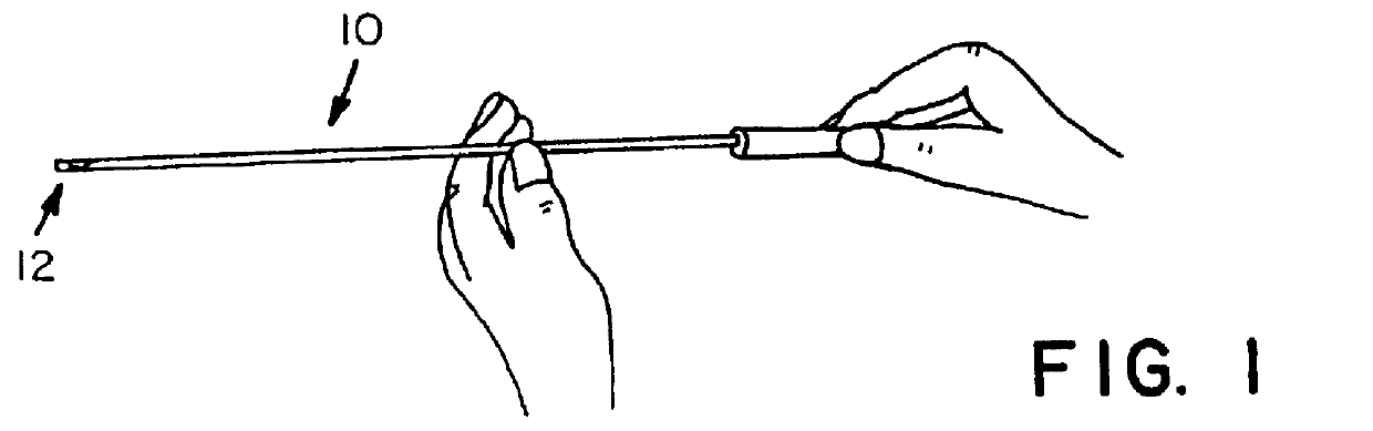
A preferred embodiment of the invention which is intended to accomplish the foregoing objects includes a fiber optic which is inserted into the lumen of a catheter and operable between an extended position wherein a distal end portion of the fiber optic is positioned to cut and vaporize a tissue body and a retracted position wherein the fiber optic is received within the lumen of the catheter. The catheter incorporates at a distal end portion a means for removing attached tissue fragments and the like from the distal end portion of the fiber optic such that tissue fragments stuck to the distal end portion of the fiber optic can be removed while the catheter and fiber remain at the treatment site. This improved system eliminates the need to completely remove the fiber optic during the cutting and vaporization procedure in order to remove the fragments and debris.

DRAWINGS

Other objects and advantages of the present invention will become apparent from the following detailed description ...


PUM


Abstract

A laser therapy system and method of cutting and vaporizing a tissue body which includes a fiber optic which is inserted into the lumen of a catheter and operable between an extended position wherein a distal end portion of the fiber optic is positioned to cut and vaporize a tissue body and a retracted position wherein the fiber optic is received within the lumen of the catheter. The catheter incorporates at a distal end portion a means for removing attached tissue fragments and the like from the distal end portion of the fiber optic such that tissue fragments stuck to the distal end portion of the fiber optic can be removed while the catheter and fiber remain at the treatment site. This improved system eliminates the need to completely remove the fiber optic during the cutting and vaporization procedure in order to remove the fragments and debris.

Description

The present invention relates to a laser therapy system and method for cutting and vaporizing a tissue body. More specifically, the invention is directed to an improved system and method for cutting and vaporizing a tissue body utilizing a fiber optic which is inserted into the lumen of a catheter and operable between an extended position wherein a distal end portion of the fiber optic is positioned to cut and vaporize a tissue body and a retracted position wherein the fiber optic is received within the lumen of the catheter. The catheter incorporates at a distal end portion a means for removing attached tissue fragments and the like from the distal end portion of the fiber optic.Laser therapy techniques have been utilized in a variety of surgical procedures in a variety of specialties for a number of years. For example, laser techniques find applications in urology, gynecology, general surgery, ENT and other surgical specialties. Generally in laser techniques, a fiber optic is inse...

Claims


Application Information

Patent Timeline
Patent Type & Authority Patents(United States)
IPC IPC(8): A61B18/20A61B18/24A61B17/22A61B17/32A61B18/00A61B19/00
CPCA61B18/24A61B19/34A61B2017/22072A61B2017/22074A61B2019/343A61B2017/320012A61B2018/0097A61B2018/00976A61B2017/22078A61B90/70A61B2090/701
Inventor HAJJAR, JOHN H.
Owner HAJJAR JOHN H
Why Eureka
Try Eureka