Motor with RPM pickup via a hall sensor

a technology of rpm pickup and hall sensor, which is applied in the direction of generator/motor, roof, instruments, etc., can solve the problems of increased assembly effort and expense, increased weight and cost, and increased installation spa

Inactive Publication Date: 2000-10-03
ROBERT BOSCH GMBH
View PDF11 Cites 56 Cited by
  • Summary
  • Abstract
  • Description
  • Claims
  • Application Information

AI Technical Summary

Problems solved by technology

Because of the additional chamber that protrudes from the inner edge of the bearing end plate, greater installation space is needed.
This dictates a large installation space.
Because power supply lines and signal lines are passed through an insulating sleeving and are guided with traction relief in recesses, greater assembly effort and expense are required on the one hand, and on the other the weight and costs rise because of the many individual parts in the installation space.

Method used


Image

  • Motor with RPM pickup via a hall sensor
  • Motor with RPM pickup via a hall sensor
  • Motor with RPM pickup via a hall sensor

Examples


Embodiment Construction

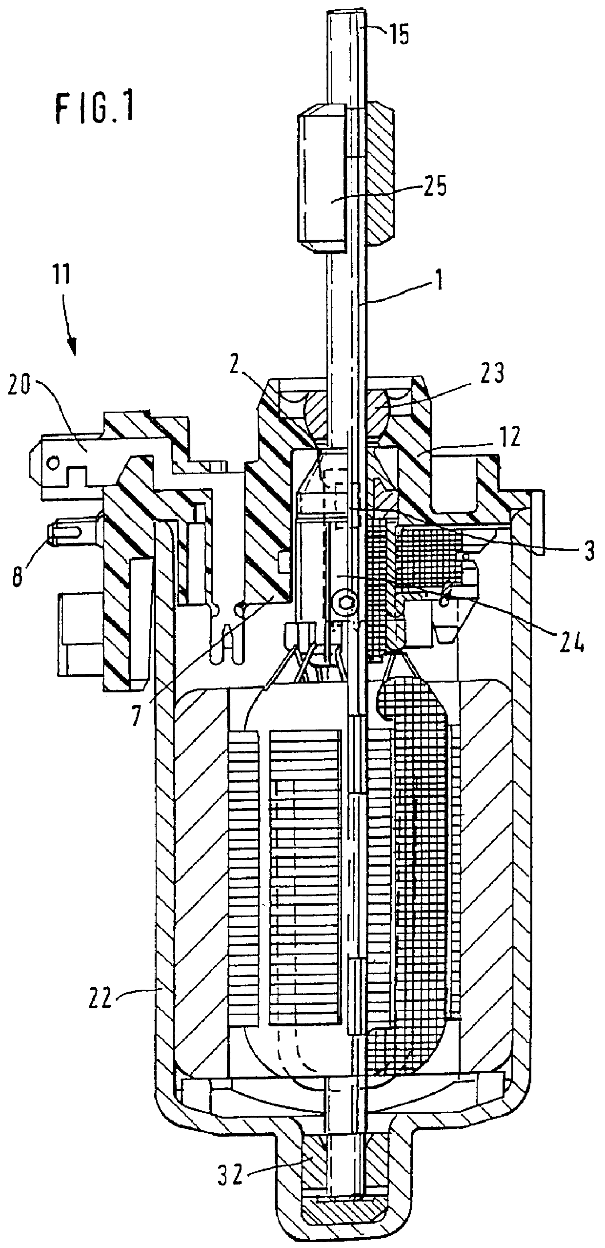
In FIG. 1, by way of example, a direct current motor with a commutator 24 is shown. The invention applies equally to alternating current and rotary current motors, but direct current motors are especially suitable for use as window raisers, sunroof actuators, seat adjusters, mirror adjusters, etc.

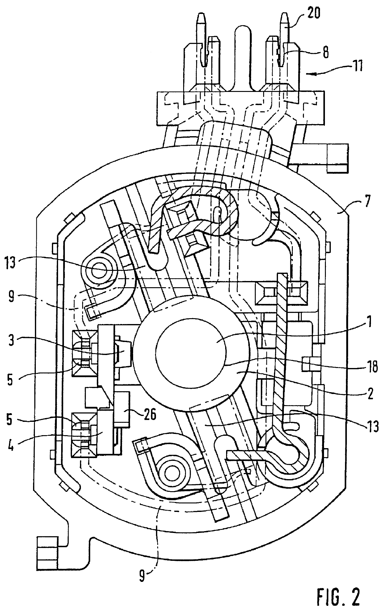
The motor has a shaft 1, which is supported in a motor housing 22 in bearings 23,32. It has a gear wheel 25, by way of which a mechanism, not shown, is driven. The motor housing 22 is closed on one end and is open on one end for installation of the internal parts of the motor. The open end is closed by a bearing cap 12, which at the same time forms a brush holder 7. A bearing 23, preferably a cup-shaped bearing, is located in the bearing cap 12.

A magnet rotor body 2 is supported on the shaft 1 with a press fit 18, between the commutator 24 and the bearing 23. The shaft 1 is axially supported on the bearing 23 by the face end 21 of the magnet rotor body 2, as long as no mechanism is yet conn...


PUM


Abstract

PCT No. PCT / DE98 / 00393 Sec. 371 Date Oct. 7, 1998 Sec. 102(e) Date Oct. 7, 1998 PCT Filed Feb. 12, 1998 PCT Pub. No. WO98 / 40751 PCT Pub. Date Sep. 17, 1998The invention is based on an electrically operated motor, having a shaft with a magnet rotor body, the RPM of the shaft can be picked up by a Hall sensor disposed on a circuit board. The circuit board is embodied with soldered pins or contact shoes and is integrated into a component of the motor, and that contacts, supply and signal lines for the circuit board are injected and / or plugged into the component of the motor.

Description

PRIOR ARTThe invention is based on a motor in which signals from a shaft are picked up by means of a Hall sensor,One such motor is known from German Patent Disclosure DE 43 26 391 A1. The motor is a direct current motor with a commutator, and it has a motor housing and a rotor with a rotor shaft, the rotor being drivable in two rotational directions. The rotor shaft is supported in two bearing end plates that close off the motor housing on two sides. A two-pole magnet rotor body is fixedly mounted on the rotor shaft. A Hall sensor is disposed on a circuit board embodied as an assembly component, which is plugged from outside into a recess of the bearing end plate. The recess has a bottom face that has a closed, indented chamber. The chamber protrudes from the inside of the bearing end plate and has a chamber wall facing the magnet rotor body. The Hall sensor is disposed behind the chamber wall at the level of the magnet rotor body and senses signals of the magnet rotor body. On the ...

Claims


Application Information

Patent Timeline
Patent Type & Authority Patents(United States)
IPC IPC(8): B60J7/057B60J7/04G01P3/487G01P3/42H02K5/14H02K23/66H02K11/00H02K5/22H02K7/116G01P3/481H02K11/21H02K11/215
CPCB60J7/0573G01P3/487H02K5/148H02K11/0021H02K23/66H02K11/0015H02K5/225H02K7/1166Y10S310/03H02K2205/06H02K2211/03Y10S310/06H02K11/21H02K11/215
Inventor WIESLER, MARTIN
Owner ROBERT BOSCH GMBH
Why Eureka
Try Eureka