Lubrication system

Inactive Publication Date: 2000-10-24
SIEMENS IND INC
View PDF7 Cites 26 Cited by
  • Summary
  • Abstract
  • Description
  • Claims
  • Application Information

AI Technical Summary

Problems solved by technology

However, certain other components are vulnerable to contamination.
This is particularly true of the work side roll shaft bearings which are located directly adjacent to the work rolls, and which are separated from externally applied cooling water and entrained particulates by complicated seal assemblies.
As the seal assemblies undergo normal wear, sealing integrity is compromised, resulting in cont

Method used


Image

  • Lubrication system
  • Lubrication system
  • Lubrication system

Examples


Embodiment Construction

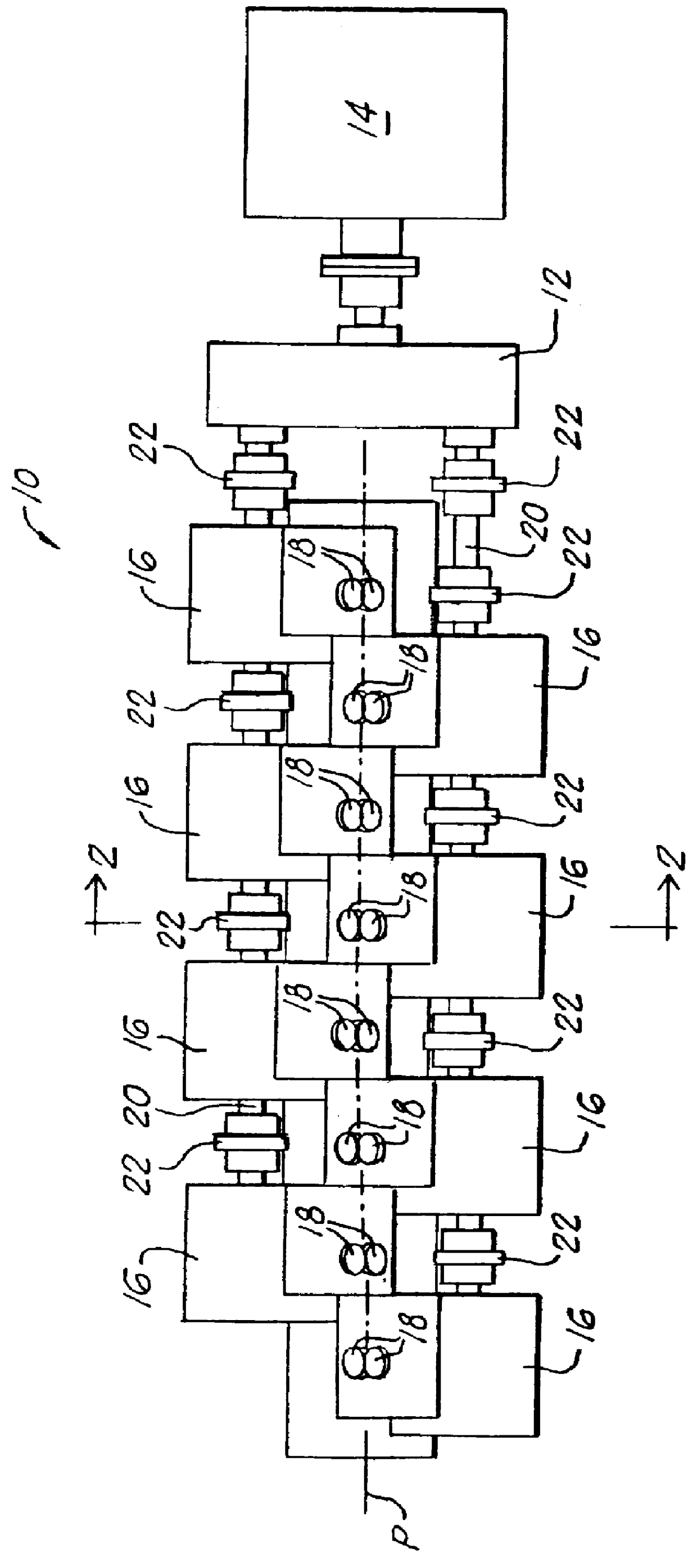
Referring initially to FIG. 1, a high speed finishing block is shown at 10. The block is powered via a gear-type speed increaser 12 by a drive motor 14.

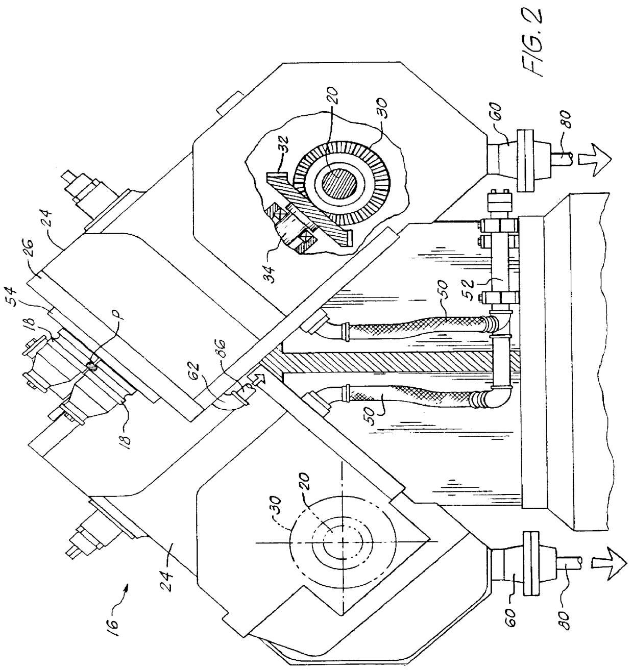
With reference additionally to FIGS. 2, 3 and 5, it will be seen that the block includes a succession of roll stands 16 alternately staggered on opposite sides of the mill pass line P. The roll stands have cantilevered pairs of work rolls 18 alternately offset by 90.degree. in order to effect twist free rolling of products. The successive roll stands on each side of the pass line are mechanically coupled one to the other and to the speed increaser 12 by line shaft segments 20 interconnected by couplings 22.

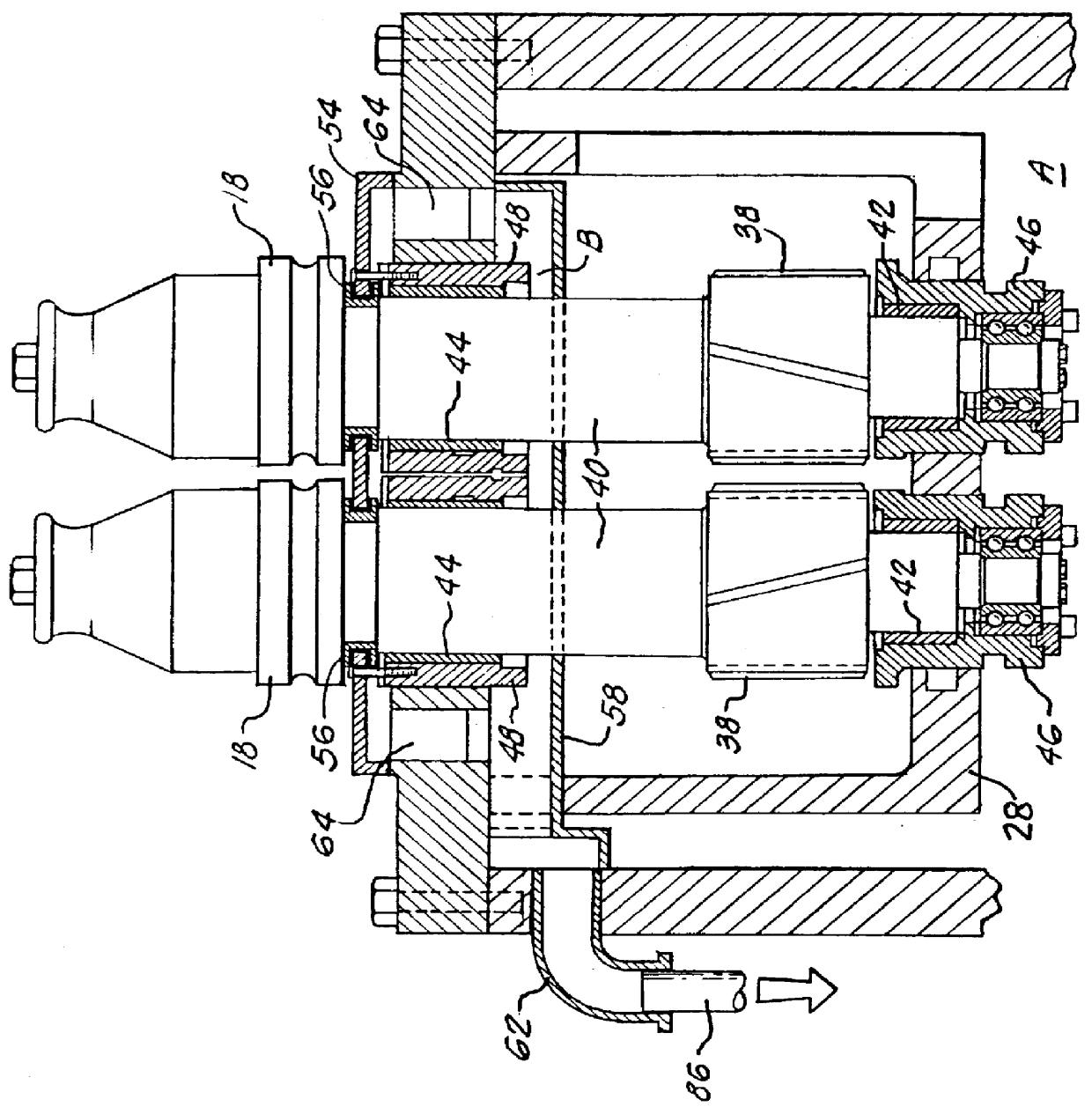
Each roll stand 16 includes a housing 24 closed at its upper end by a front plate 26 supporting an internally protruding open sided cartridge body 28. Within each housing 24, the respective line shaft segment 20 carries a bevel gear 30 meshing with a mating bevel gear 32 on one of a pair of parallel drive shafts 34. The drive shaft...


PUM

PropertyMeasurementUnit
Partition functionaaaaaaaaaa

Abstract

A system is disclosed for applying a liquid lubricant to first and second components enclosed in a housing, with the lubricant applied to the second components being exposed to contamination by a liquid coolant applied to the exterior of the housing, and with the lubricant applied to the first components being substantially isolated from the liquid coolant. The system includes a partition internally subdividing the housing into a first chamber containing the first components and a second chamber containing the second components. Lubricant is delivered from a storage tank to the housing for application to the first and second components. A first conduit network communicates with the first chamber for returning the lubricant applied to the first components to the storage tank, and a second conduit network communicates with the second chamber for returning lubricant applied to the second components to the storage tank. A liquid coolant removal unit in the second conduit network removes liquid coolant from the lubricant being returned to the storage tank.

Description

1. Field of the InventionThis invention relates generally to lubrication systems, and is concerned in particular with although not limited to rolling mill lubrication systems where a liquid lubricant is applied to multiple components and where some but not all of the thus applied lubricant is susceptible to being contaminated by externally applied cooling water and entrained particulates, e.g., dirt, mill scale, etc.2. Description of the Prior ArtIn a conventional rolling mill lubrication system, for example that employed with a high speed finishing block of the type described in U.S. Pat. No. 5,577,405 (Shore et al.), a liquid lubricant is pumped from remote storage tanks for delivery to the individual roll stands, where it is applied via internal networks to the bearings, gears and other associated components housed within the roll stands. At the same time, cooling water is continuously applied externally to the work rolls and associated guides.The majority of the internal compone...

Claims


Application Information

Patent Timeline
IPC IPC(8): B21B45/02B21B31/07B21B31/00B21B31/16B21B35/00B21B35/02B21B31/26B21B13/00B21B27/06B21B27/10F16H57/04F16N7/14
CPCB21B31/076F16H57/04B21B45/0296B21B13/005B21B31/078B21B35/02B21B31/26Y02P70/10B21B27/06
Inventor SHORE, T. MICHAELPUCHOVSKY, MELICHER
Owner SIEMENS IND INC
Why Eureka
Try Eureka