Differential pressure forming, trimming and stacking apparatus

a technology of different pressure and forming apparatus, applied in dough shaping, manufacturing tools, food shaping, etc., can solve the problems of inability to consistently control the batch to batch chemistry of plastic, the removal of parts from the mold, and the relatively slow process

Inactive Publication Date: 2000-10-24
BROWN MACHINE OF MICHIGAN
View PDF15 Cites 55 Cited by
  • Summary
  • Abstract
  • Description
  • Claims
  • Application Information

AI Technical Summary

Problems solved by technology

A problem attendant to the machines which trim parts in a thermoplastic sheet is the removal of parts from the mold.
This is a relatively slow, time consuming process.
A problem with this prior art construction which differential pressure forms at an upstream forming station and trims the part from the sheet at a downstream trimming station is the complications resulting from the inability to consistently control the batch to batch chemistry of the plastic.
When the articles are transferred to the downstream trim station, the parts may not be precisely aligned with the trim mold to precisely allow accurate trimming.
The cutting force required to sever the sheet is rather large and the force exerted by a cam, as disclosed in Kiefer, is sometimes insufficient to properly sever the sheet.
There are several problems attendant to this construction illustrated in this latter patent including the inability to efficiently and accurately transfer the formed and severed parts to a stacker.
The construction illustrated in this German publication also is of limited value, however, in that the apparatus only rotates the lower platen and mold thereon and does not bodily move the lower mold horizontally toward the stacker after it is rotated to its lowermost position.
It is difficult to transfer the articles in the mold from the mold to the receiver.
Consequently, due to the great distance through which the article must be propelled to reach the stacker tremendously large ejection force is required to physically propel the articles from the mold through the gap to the stacker.
One of the other problems with the prior art constructions is that the articles, which typically include hollow, then walled plates, cups, and the like are held in the stacker by circumferentially disposed brushes which are intended to grip the circumferential edge but don't always hold the hollow articles in proper alignment to be stacked with successively discharged articles.
This delay in ejection increases the production time and is relatively inefficient.
The retraction of the prior art mold to the forming station does not commence until the bottom wall is retracted which takes substantial time and delays the overall production time.

Method used


Image

  • Differential pressure forming, trimming and stacking apparatus
  • Differential pressure forming, trimming and stacking apparatus
  • Differential pressure forming, trimming and stacking apparatus

Examples


Embodiment Construction

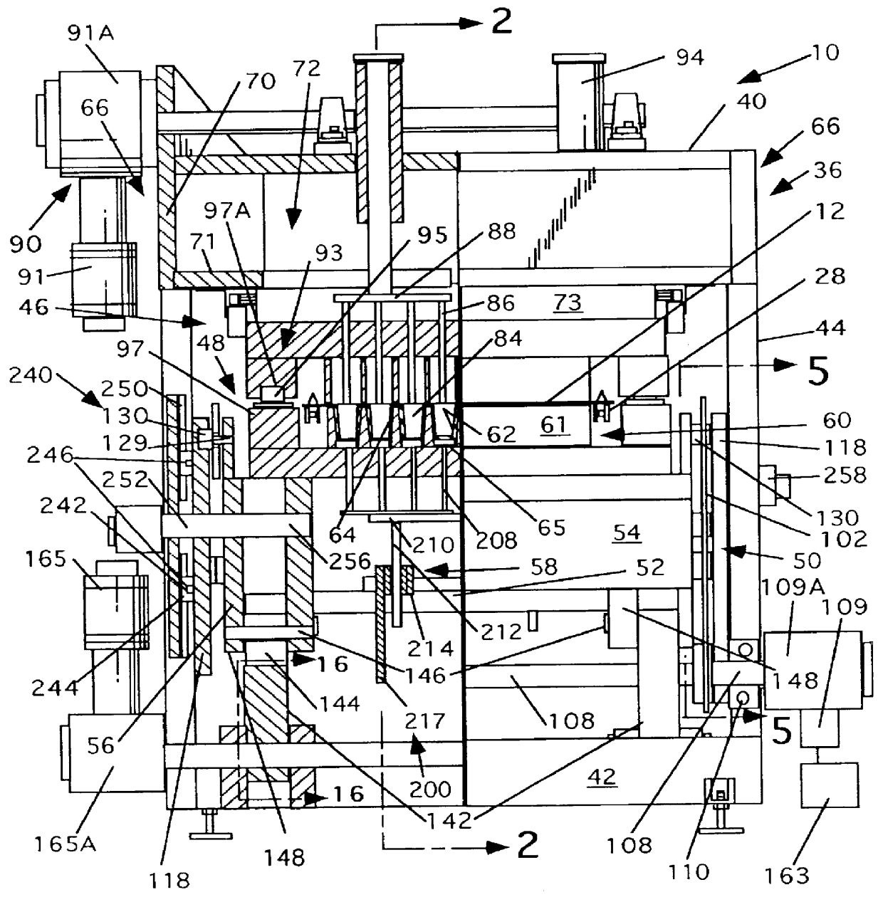
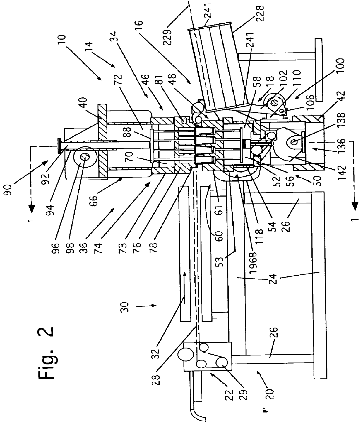
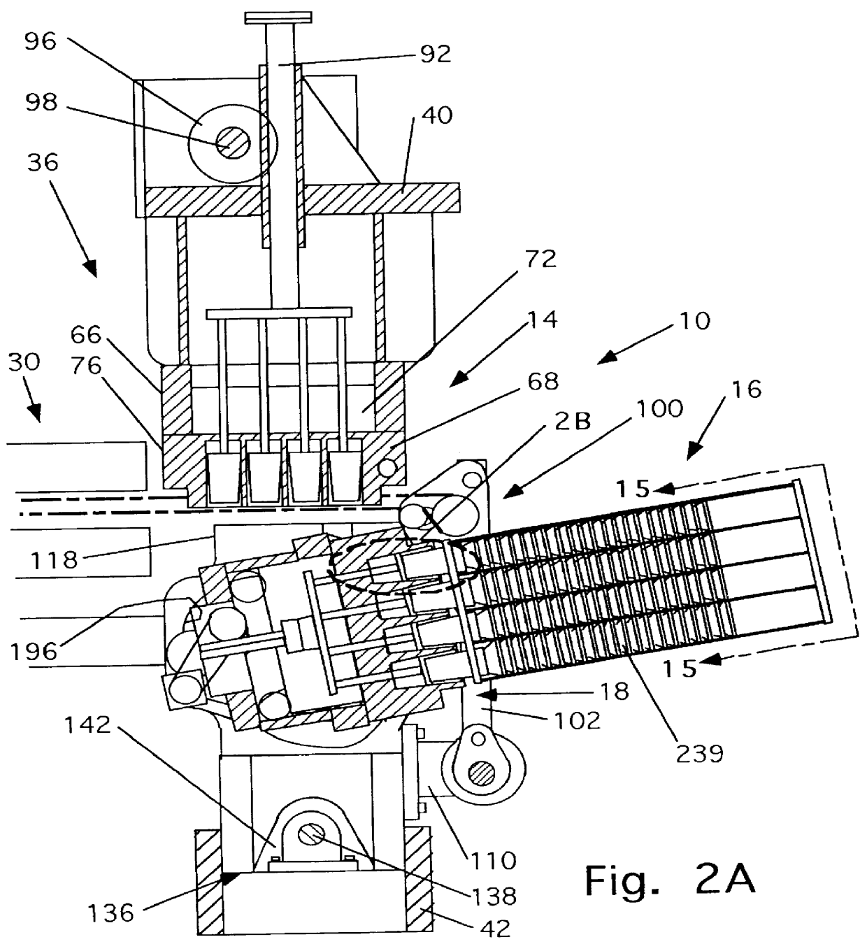
Apparatus constructed according to the present invention, generally designated 10, is provided for differentially pressure forming an article A (FIG. 6B) in a thermoplastic sheet 12 of thermoplastic material at a mold and trim station 14, trimming the article A from the sheet 12 at the mold and trim station 14, and transferring the severed article A from the mold and trim station 14 to a stacker 16 at a discharge station 18.

The differential pressure forming, trimming and stacking apparatus 10 includes a frame, generally designated 20, sheet supply mechanism, generally designated 22, and a tunnel oven, generally designated 30. The frame 20 includes horizontal, vertically spaced apart, side rails 24 spanned by vertical rails 26 which mount laterally spaced apart chains 28, driven by frame mounted motor 29 for carrying a continuous sheet 12 of thermoplastic material in a downstream path of travel, represented by the arrow 32, to the tunnel oven 30 and thence to the mold and trim statio...


PUM

PropertyMeasurementUnit
angleaaaaaaaaaa
reorientation angleaaaaaaaaaa

Abstract

Apparatus for forming articles in a thermoplastic sheet, severing the articles in the sheet, and stacking the articles in a stacking receiver. The apparatus includes upper and lower molds moveable between closed positions in which the molds engage opposite sides of the sheet to differentially pressure form a part in the thermoplastic sheet. The molds in which the article is formed are moved toward each from the closed positions to article trim positions to sever the article from the sheet. The lower mold is then moved linearly away from the sheet in a vertical direction and then transversely moved in a second linear transverse path of travel to a remote discharge location. Apparatus is provided for reorienting the mold between its orientation in the first linear path of travel and its orientation in the second path of travel.

Description

1. Field of the InventionThis invention relates to differential pressure forming apparatus and more particularly to transfer apparatus for transferring an article differentially pressure formed in, and trimmed from, a thermoplastic sheet at a form and trim station to a vertically lowered and horizontally displaced discharge station.2. Description of the Prior Art and ObjectsApparatus, such as that disclosed in U.S. Pat. No. 5,585,689 issued to G. W. Brown, et al on Jun. 22, 1971, and U.S. Pat. No. 4,313,358 issued to Gaylord W. Brown on Feb. 2, 1982, which are each incorporated herein by reference, has been provided heretofore for trimming articles, differentially pressure formed in a thermoplastic sheet, at a trimming station which is downstream of a forming station. U.S. Pat. No. 5,225,213 issued to G. W. Brown and Albert W. Arends on Jul. 6, 1993, discloses apparatus for trimming an article from a thermoplastic sheet including a wedge for incrementally moving a trim die from a re...

Claims


Application Information

Patent Timeline
Patent Type & Authority Patents(United States)
IPC IPC(8): B29C51/44B29C51/18B29C51/26B29C51/32B29C51/30B29C51/04B29C51/00
CPCB29C51/18B29C51/44B29C51/26B29C51/04B29C51/32
Inventor ARENDS, ALBERT W.
Owner BROWN MACHINE OF MICHIGAN
Why Eureka
Try Eureka