Concave probe for arthroscopic surgery

a probe and arthroscopic technology, applied in the field of medical devices, can solve the problems of poor adaptability of current probes to certain activities, surgeons have little control when pressing against tough ligaments, and limitations of arthroscopic surgery

Inactive Publication Date: 2000-10-24
ORATEC INTERVENTIONS
View PDF173 Cites 425 Cited by
  • Summary
  • Abstract
  • Description
  • Claims
  • Application Information

AI Technical Summary

Problems solved by technology

Nevertheless, arthroscopic surgery has its limitations.
The surgeon must operate through a narrow tube, which is awkward.
However, current probes are poorly adapted to certain activities, such as cutting narrow tendons or ligaments.
With current probes, the surgeon has little control when pressing against a tough ligament.
The surgeon must reapproximate the probe and cut again, an inefficient process.
And, unless the surgeon is able to stop pressure at exactly the right time, the probe may slip and cut an adjacent structure.
Because the surgeon must repeatedly reapproximate and cut the ligament, the surgeon has difficulty in cleanly ablating the ligament or tendon.
Unfortunately, this often results in bigger scars, longer convalescence, and more irritation of an already irritated joint.

Method used


Image

  • Concave probe for arthroscopic surgery
  • Concave probe for arthroscopic surgery
  • Concave probe for arthroscopic surgery

Examples


example 1

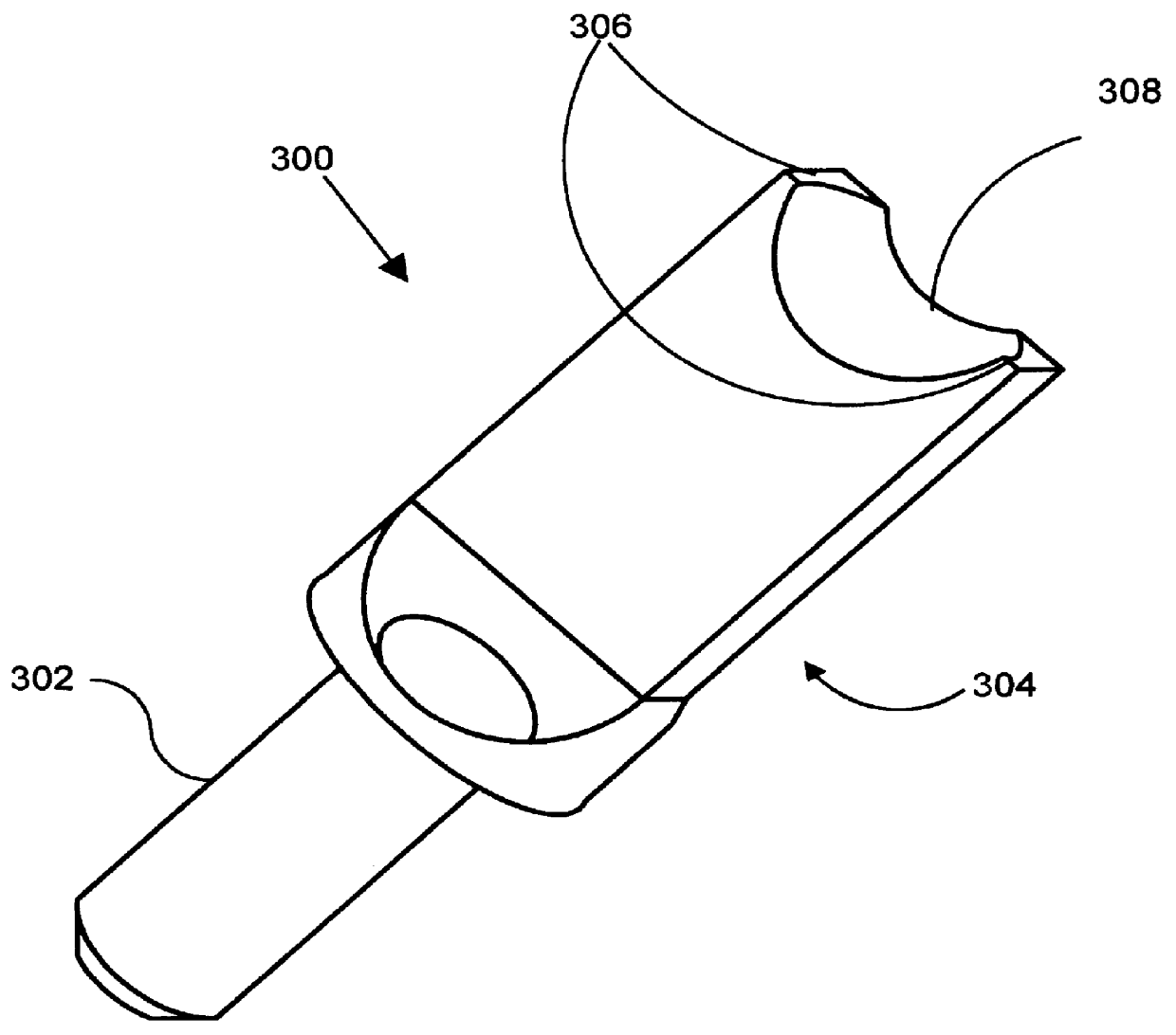
Lateral retinacular release as mentioned above can be accomplished with the use of the concave-tipped RF probe as shown in FIG. 3. First, the knee joint is distended with a clear fluid, usually saline. Initial distention can be done using a large syringe full of saline which is injected into the joint space. Distention forces the bones of the joint apart creating room to introduce instrumentation without damaging the cartilage.

Once the instrumentation has been inserted into the joint space, the irrigation tubing and cannulas are positioned and hooked up to provide continual fluid exchange during the procedure. The most common systems are gravity flow or the use of an arthroscopic irrigation pump. Just hanging bags of irrigation fluid on an IV pole raises them 3-4 feet above the operative site. This elevation difference is enough to create pressure to distend and irrigate the joint. The fluid enters the joint through the scope sheath and exits through a cannula placed in the superior...


PUM


Abstract

Disclosed herein is a new arthroscopic probe with a concave distal tip which simultaneously constrains and cuts tissue. It is particularly adapted to cutting ligaments and tendons. Also disclosed is a thermal energy delivery apparatus which includes (a) a probe means with a distal end and a proximal end, wherein the distal end has a concave tip; (b) a first electrode means positioned at the distal end of the probe means, wherein the first electrode means is configured to deliver sufficient thermal energy to cut ligaments or tendons; and (c) a cabling means coupled to the proximal end of the probe means. In another embodiment of the invention a controller for controlling the delivery of energy and liquid to a surgical instrument with a temperature sensor is disclosed. The energy is supplied by an energy source and the liquid is supplied by a pump. The controller includes a temperature and a flow regulator. The temperature regulator is coupled to the energy source and coupled to the pump. The temperature regulator is responsive to a first temperature indication from the temperature sensor to determine that the first temperature indication exceeds a setpoint and to reduce an energy level from the energy source. The flow regulator is coupled to the pump and coupled to the temperature regulator. The flow regulator includes responsiveness to the first temperature indication to increase a flow of the liquid from the pump.

Description

1. FIELD OF USEThe present invention is in the field of medical devices which deliver radio-frequency energy to cut tissue. More specifically, the invention is in the field of cutting probes for arthroscopic surgery.2. BACKGROUNDArthroscopic surgery is becoming increasingly popular, because it generally does less damage than open procedures, produces less scarring in and around joints, and results in faster healing and return of the patient to full productivity.Nevertheless, arthroscopic surgery has its limitations. The surgeon must operate through a narrow tube, which is awkward. Only one probe can be used at a time. Often the viewing camera is positioned at an angle different from the surgeon's normal gaze. This contrasts with "open surgery" where the surgeon has relative ease of viewing the surgical site and can freely move both hands, even utilizing the hands of colleagues.In view of such difficulties of arthroscopic surgery, it is understandable that laser, microwave and radio-...

Claims


Application Information

Patent Timeline
Patent Type & Authority Patents(United States)
IPC IPC(8): A61B18/14A61N1/40A61N1/06A61B17/32A61B17/16
CPCA61B17/1626A61N1/40A61B17/1684A61B18/148A61N1/06A61B17/1659A61B17/1675A61B2017/320008A61B2018/00434A61B2018/00625A61B2018/00654A61B2018/00702A61B2018/00791A61B2018/00797A61B2018/1472A61B2218/002
Inventor FANTON, GARY S.SHARKEY, HUGH R.STEWART, DAREN L.WEISSMAN, LEE
Owner ORATEC INTERVENTIONS
Why Eureka
Try Eureka