Adjustable spoiler support for racing car

Inactive Publication Date: 2000-10-31
STIDD ROBERT S
View PDF11 Cites 41 Cited by
  • Summary
  • Abstract
  • Description
  • Claims
  • Application Information

AI Technical Summary

Benefits of technology

It is another object of the invention to provide a spoiler support which is strong enough to resist speed-induced forces and yet light

Problems solved by technology

Use of prior art devices under these circumstances is difficult, since the brackets must

Method used


Image

  • Adjustable spoiler support for racing car
  • Adjustable spoiler support for racing car
  • Adjustable spoiler support for racing car

Examples


Example

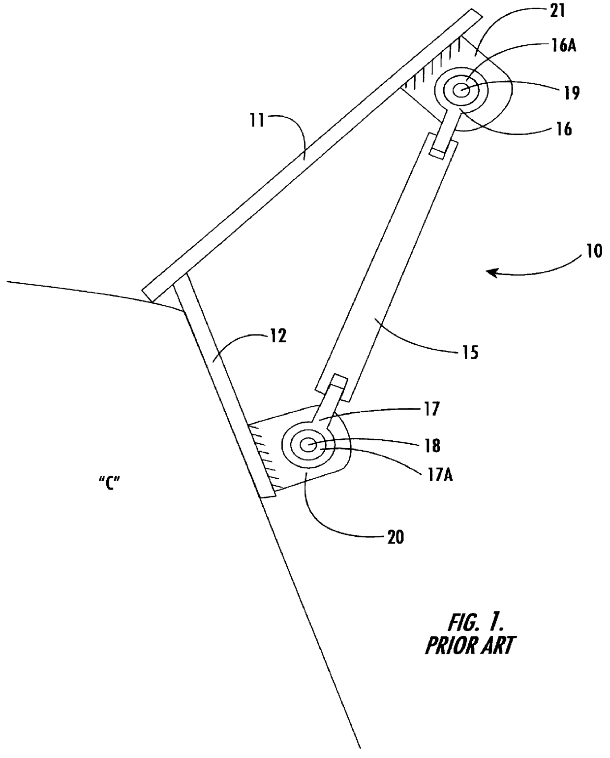
Referring now specifically to the drawings, a spoiler support according to the prior art is illustrated in FIG. 1 and shown generally at reference numeral 10. The spoiler support 10 is mounted between a spoiler 11 and a mounting plate 12 secured to the race car "C." The spoiler support 10 is formed from an elongate rod 15 threaded on opposite ends to receive Heim joints 16 and 17. The Heim joints include annular inserts 16A and 17A through which are extended pins 18 and 19. The pins 18 and 19 are captured by brackets 20 and 21 which are welded to the mounting plate is and spoiler 11, respectively. As is apparent from FIG. 1, the spoiler support 10 must be mounted in alignment with the mounting axis of the brackets 20 and 21. If and when a change in mounting alignment is required, the brackets must be removed, repositioned, and rewelded.

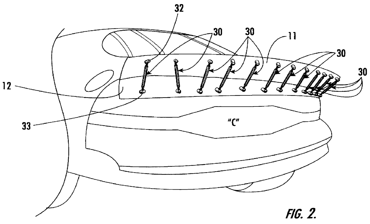
Referring now to FIG. 2, racing car "C" is shown with the spoiler 11 being supported by twelve spoiler supports 30 according to the present invention...


PUM


Abstract

An adjustable spoiler support for adjustably supporting a aerodynamic spoiler relative to a racing car body, including an elongate support bar having opposite first and second ends and gimbals having at least two axes of movement carried by the support bar for permitting two-axis adjusting movement of the spoiler support. Attachments are provided for attaching the first end of the support bar to the spoiler and the second end of the support bar to the car body. The gimbals have at least first and second axes of movement.

Description

TECHNICAL FIELD AND BACKGROUND OF THE INVENTIONThis invention relates to an adjustable spoiler support for a racing car, for example, "stock cars" of the type which race in various series of NASCAR-sponsored races. Spoilers deflect upwardly air which is smoothly flowing across the very aerodynamic top surface of the racing car and creates a reactive downward thrust which tends to increase traction between the rear wheels of the car and the track. The angle with which the spoiler is extended into the airstream determines the downward force exerted by the deflected air on the spoiler.A spoiler is generally formed of a thin blade of metal which is attached by an elongate bracket to, and extends transversely across, the rear of the car. The force of the air being deflected by the spoiler is sufficiently great that the spoiler itself would be deflected downwardly out of the air flow unless supported in its predetermined angled position. Thus, it is typical to cantilever the spoiler in it...

Claims


Application Information

Patent Timeline
IPC IPC(8): B62D35/00
CPCB62D35/007Y10S180/903
Inventor STIDD, ROBERT S.
Owner STIDD ROBERT S
Why Eureka
Try Eureka