Toric multifocal lens having different astigmatism corrective optical powers in respective vision correction regions, and method of producing the same

Inactive Publication Date: 2000-11-07
MENICON CO LTD
View PDF13 Cites 174 Cited by
  • Summary
  • Abstract
  • Description
  • Claims
  • Application Information

AI Technical Summary

Problems solved by technology

The above-described conventional toric multifocal lens is, however, unsatisfactory to some patients whose eyes suffer from presbyopia as well as astigmatism, even when the conventional toric multifocal lens has a suitably determined spherical optical power for correction of presbyopia and a cylindrical optical power for correction of astigmatism.
In particular, the conventional toric multifocal lens whose cylindr

Method used


Image

  • Toric multifocal lens having different astigmatism corrective optical powers in respective vision correction regions, and method of producing the same
  • Toric multifocal lens having different astigmatism corrective optical powers in respective vision correction regions, and method of producing the same
  • Toric multifocal lens having different astigmatism corrective optical powers in respective vision correction regions, and method of producing the same

Examples


first embodiment

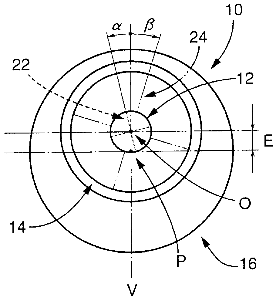
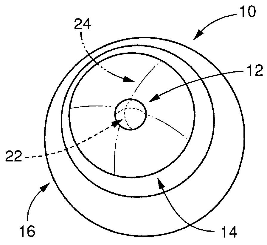
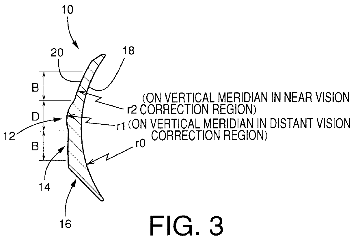
Referring first to FIG. 1, there is shown a toric multifocal lens in the form of a presbyopia correction contact lens 10 constructed according to the present invention. FIG. 1 is a perspective front view of the contact lens 10 showing its front surface, while FIGS. 2 and 3 are a plan view and a cross sectional view of the contact lens 10, respectively. The presbyopia correction contact lens 10 of the present embodiment includes, at a substantially central portion thereof, a circular near vision correction region 12 having a diameter D (FIG. 3), and an annular distant vision correction region 14 surrounding the near vision correction region 12 and having a width B (FIG. 3). The near and distant vision correction regions 12, 14 cooperate with each other to constitute an optical zone which exhibits an intended vision correct ion performance. An annular portion 16 located radially outwards of the distant vision correction region 14, in other words, the radially outermost portion 16 of t...

second embodiment

Referring next to FIG. 4, there is shown a toric multifocal lens in the form of a translating vision type, presbyopia correction contact lens 26 constructed according to the present invention. FIG. 4 is a perspective front view of the contact lens 26 showing its front surface, while FIGS. 5 and 6 are a plan view and a cross sectional view of the contact lens 26, respectively. The presbyopia correction contact lens 26 of the present embodiment consists of a substantially circular distant vision correction region 28 having a diameter d (FIG. 5) and formed at a central portion of the lens 26, and a near vision correction region 30 surrounding the distant vision correction region 28. The near and distant vision correction regions 28, 30 cooperate with each other to constitute an optical zone which exhibits an intended vision correction performance. As shown in FIG. 5, the distant and near vision correction regions 28, 30 have a common optical center axis O which is offset from a geometr...


PUM

PropertyMeasurementUnit
Angleaaaaaaaaaa
Poweraaaaaaaaaa
Radiusaaaaaaaaaa

Abstract

A toric multifocal lens including a plurality of vision correction regions having centers on a common optical center axis, the plurality of vision correction regions providing respective different values of a spherical optical power, each of the plurality of vision correction regions having an optical power for correction of astigmatism, wherein the improvement comprises: at least one of a cylindrical optical power and a cylindrical axis orientation which determine the optical power for correction of astigmatism being different in at least two different vision correction regions of the plurality of vision correction regions, so that the at least two different vision correction regions have respective different values of the optical power for correction of astigmatism.

Description

The present application is based on Japanese Patent Application No. 10-98939 filed Apr. 10, 1998, the content of which is incorporated hereinto by reference.1. Field of the InventionThe present invention relates to a toric multifocal lens and its related technique, which toric multifocal lens includes a plurality of vision correction regions that provide respective different values of astigmatism corrective optical power, the respective vision correction regions having different values of spherical optical power. In particular, the present invention is concerned with such a toric multifocal lens suitably used as an ophthalmic lens such as a contact lens or an intraocular lens, for correcting a lens wearer's vision which is deteriorated due to decreasing accommodation of the eye, and for correcting astigmatism. The present invention is also concerned with a method of producing the toric multifocal lens, and a cutting apparatus used for cutting a lens blank to form the toric multifoca...

Claims


Application Information

Patent Timeline
IPC IPC(8): G02C7/04G02C7/02A61F2/16B23B5/00G02B3/06G02C7/06
CPCG02C7/042G02C7/043G02C7/048G02C7/044G02C2202/04
Inventor SAWANO, TADASHIOYAMA, HIROYUKIKONDOU, HIDEAKIGOTOU, YUUZI
Owner MENICON CO LTD
Why Eureka
Try Eureka