Polishing machine

a polishing machine and polishing technology, applied in the direction of polishing machines, grinding drives, manufacturing tools, etc., can solve the problems of increasing the need for more slurry, unable to efficiently hold, and reducing the efficiency of slurry utilization

a polishing machine and polishing technology, applied in the direction of polishing machines, grinding drives, manufacturing tools, etc., can solve the problems of increasing the need for more slurry, unable to efficiently hold, and reducing the efficiency of slurry utilization

US6146260AInactive Publication Date: 2000-11-14INFINEON TECH AG +2

Image

  • Polishing machine
  • Polishing machine
  • Polishing machine

Examples


Embodiment Construction

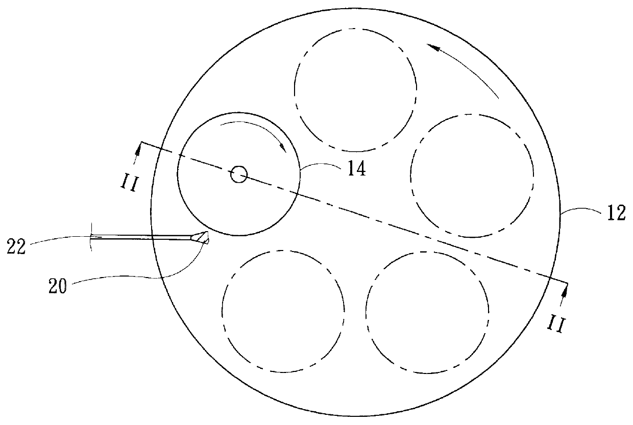
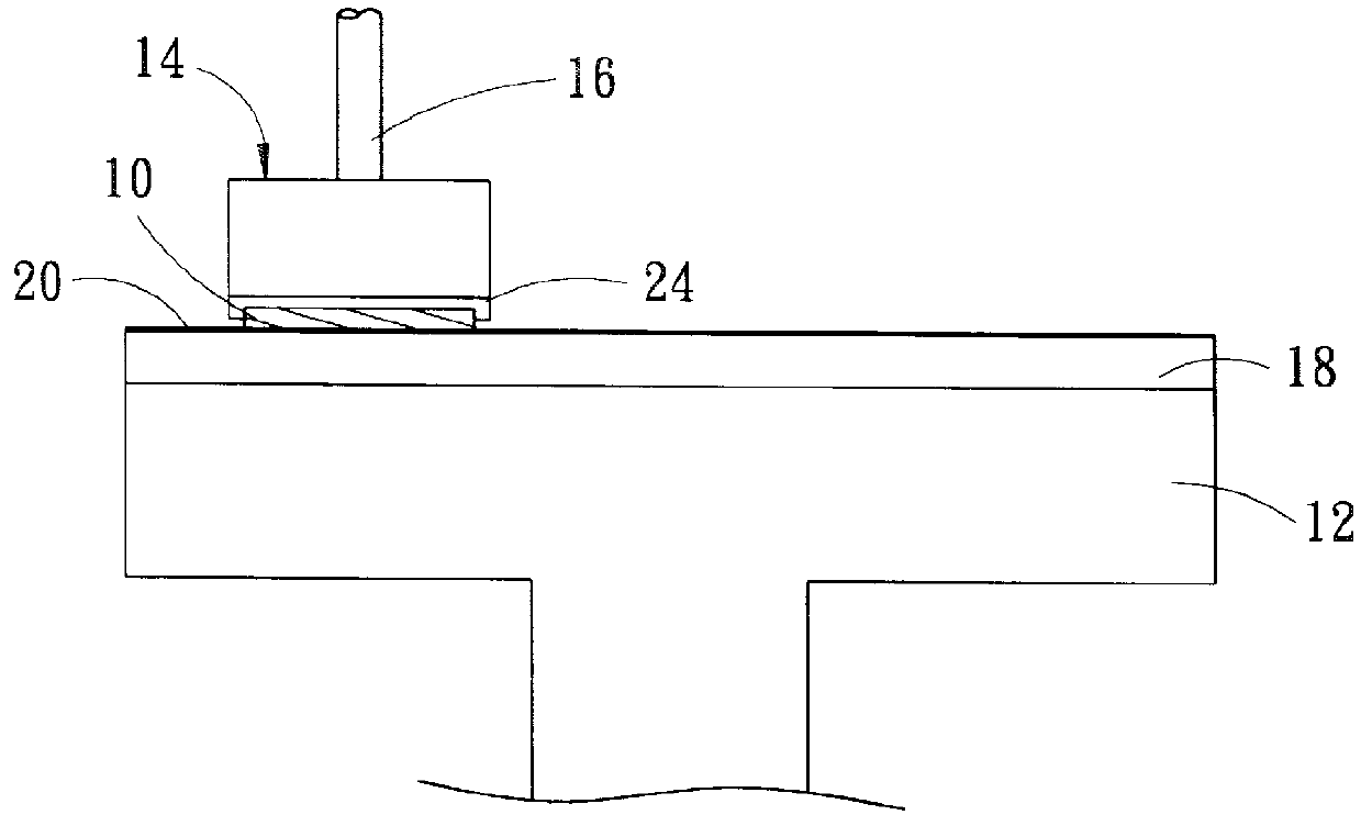
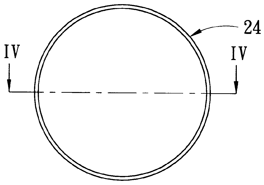
As in the above description, FIG. 1 to FIG. 6 illustrate a CMP machine and wafer adapters of prior arts.

FIG. 7 and FIG. 8 illustrate a bottom view and sectional view of a wafer adapter according to the present invention, respectively. The adapter includes a retaining ring 32 for grasping a wafer of smaller size (such as 6 inches diameter) and an unshown fastener such as a screw for fastening the ring to a holder 16 (see FIG. 2) of an original designed larger diameter (such as 8 inches) wafer CMP machine. There are multiple grooves 39 having a bowl-like cross-section formed on the lower surface of the ring 32 the inner surface of the ring 32 defines a cavity which is dimension to just grasp a wafer. The bowl-like grooves 39 have narrower openings 361 at the outer circle and wider bottoms 362 at the inner circle of the ring 32; and the bottoms 362 are apart from the inner circle with a wall 363 having a thickness less than 0.5 centimeters. There is also a carrier film 34 laid between ...


PUM


Abstract

A wafer adapter for a chemical and mechanical polishing (CMP) machine. The adapter includes a retaining ring with multiple grooves formed on one surface of the ring and an inner circle for grasping just a wafer. The grooves have narrower openings at the outer and wider bottoms at the inner circle of the ring. The bottoms are apart from the inner circle with a circular wall. The adapter with wedged grooves served as slurry pools has been proved to have higher polishing efficiency, no wafer lose by sharp edges collision on the wall and less contact pressure between the wafer and the adapter to extend the lifetime of the adapter.

Description

1. Field of the InventionThe present invention relates to a Chemical-Mechanical Polishing (CMP) machine for polishing semiconductor wafers and, more particularly, to a wafer adapter for adapting a wafer in such a polishing machine.2. Description of Related ArtCMP is a technology in the process for global planarization of a semiconductor wafer for VLSI (very large scaled integrated circuit) or ULSI (ultra large scaled integrated circuit). It utilizes a mechanical polishing method with a chemical reagent for polishing the surface of the wafer to provide planarity for the outer surface.Referring to FIG. 1 and FIG. 2, a plane view and a sectional view of a conventional CMP machine are shown, respectively. It includes a polishing table 12 and at least one carrier 14 located upon the table for holding a wafer 10 which will be polished. The carrier 14 further includes a holder 16 and an adapter 24 for grasping the back of a wafer 10 and pressing the exposed surface of the wafer on a polish...

Claims


Application Information

Patent Timeline
14 Nov 2000
Publication
US6146260A
IPC
B24B37/04; B24B37/32; H01L21/304; H01L21/683
CPC
B24B37/32
Inventors
YI, CHAMPION