Shape-adjusting mechanism

a technology of adjusting mechanism and adjusting plate, which is applied in the direction of stools, seating furniture, domestic applications, etc., can solve the problems of not being able to specify the profile ultimately presented and not being able to conform to the curvature of the user's spine in a way that is convenient for users, and achieves low bending resistance and high bending resistan

Inactive Publication Date: 2000-11-28
SCHUKRA MFG
View PDF32 Cites 42 Cited by
  • Summary
  • Abstract
  • Description
  • Claims
  • Application Information

AI Technical Summary

Benefits of technology

In one aspect, the invention provides a shape-adjusting mechanism insertable into a backrest to present a desired profile. The mechanism includes a lumbar basket which has a pair of supports spaced-apart along an axis. One or more resilient axial ribs are fixed to the supports so that the axial ribs flex in a predetermined direction as the supports are displaced towards one another, and resilient traverse ribs are fixed to the axial ribs. Means are provided to displace the supports to flex the axial ribs. To control flexing, each axial rib is structured to have lengthwise sections with different resistance to bending in the predetermined direction. For example, each axial rib may have a lengthwise section of relatively low bending resistance proximate to a selected support and another lengthwise section of relatively high bending resistance proximate to the other support. The flexing of the axial ribs is thus more pronounced proximate to the selected support, and the lumbar basket may be installed in a backrest with the selected support lowermost where the pronounced flexing better conforms to the curvature of a users spine. More generally, lengthwise sections of different bending resistance can be located along each axial rib to achieve various preselected profiles which are felt to be appropriate. This approach eliminates the need to make additional components, such as partial stiffening ribs, and to affix such additional components to the basket.

Problems solved by technology

The basic lumbar basket described above has a flexed profile which is essentially a segment of a circle, and consequently does not conform adequately to the curvature of a user's spine.
Making the partial rib and then fastening it to multiple components of the basic lumbar basket contributes to cost There is also little freedom to specify the profile ultimately presented by the basket.

Method used


Image

  • Shape-adjusting mechanism
  • Shape-adjusting mechanism
  • Shape-adjusting mechanism

Examples


Embodiment Construction

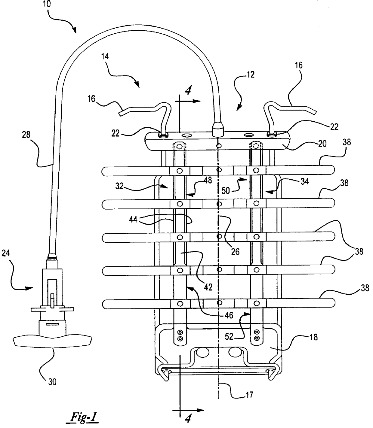
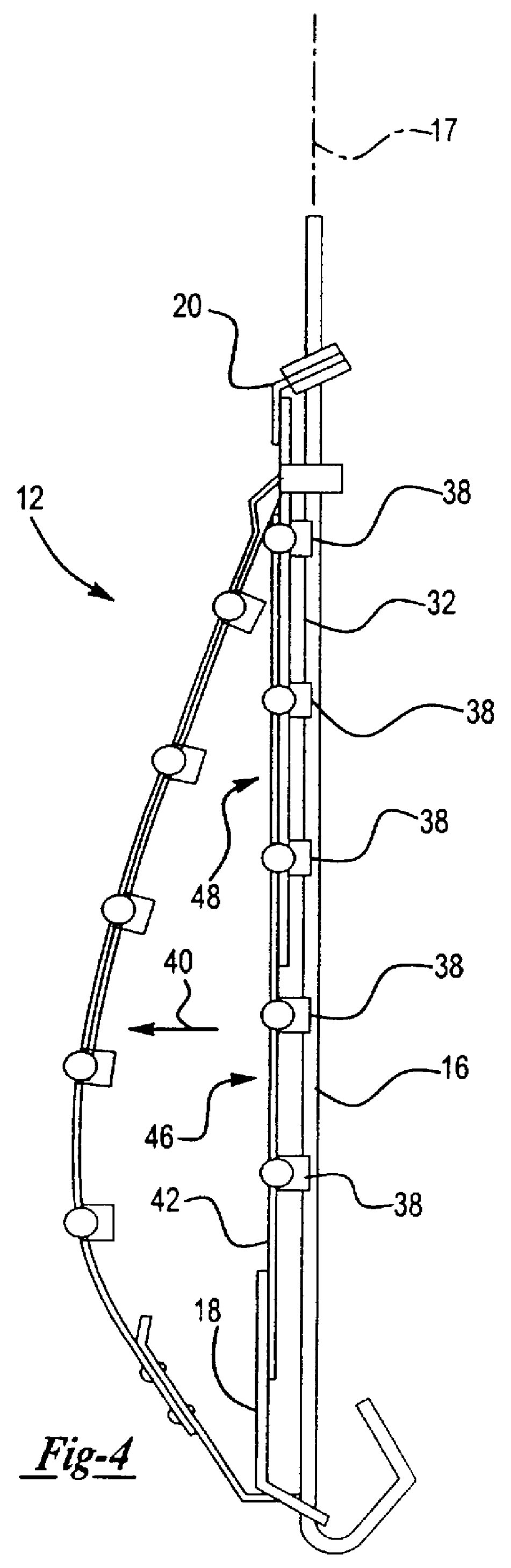
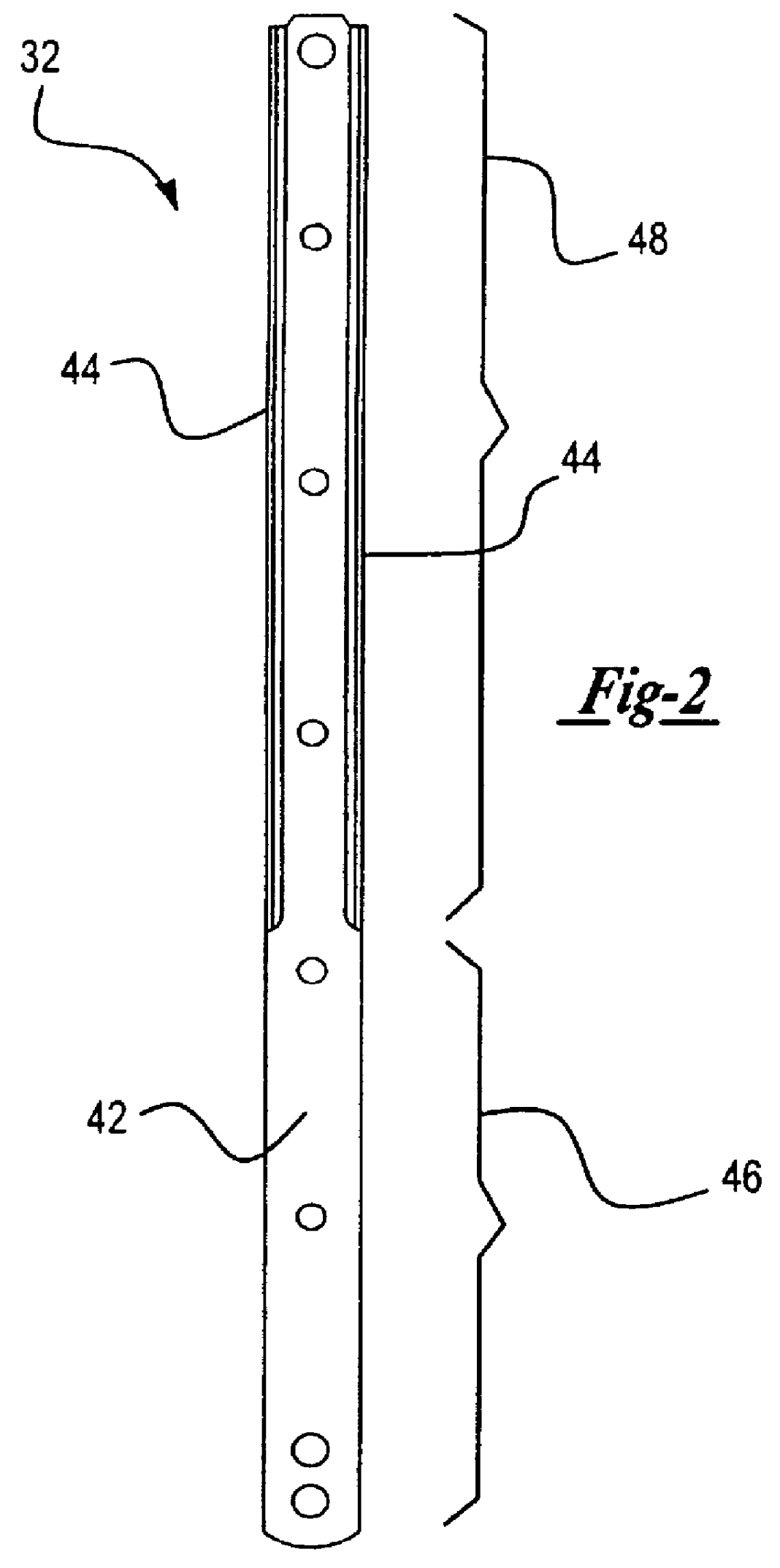
A general description will be provided with reference to FIGS. 1-4 of a shape-adjusting mechanism 10 insertable into a backrest (not illustrated). The mechanism 10 includes a lumbar basket 12 and a guide track 14 which consists of a pair of steel rods 16 in general alignment with an axis 17. The lumbar basket 12 has a pair of steel brackets (supports) 18, 20. The upper bracket 20 carries a pair of low-friction sleeves 22 that receive the rods 16 of the guide track 14. The lower bracket 18 is similar adapted for retention and displacement on the rods 16. A conventional cable mechanism 24 can be manually operated to flex the lumbar basket 12. The mechanism 24 includes a cable 26 attached to the lower bracket 18 and extending through the upper bracket 20, and a sheath 28 surrounding the cable 26 and butted against the upper bracket 20. A handle 30 can be rotated to draw the cable 26 through the sheath 28, displacing the brackets 18, 20 axially towards one another and flexing the basket...


PUM

PropertyMeasurementUnit
angleaaaaaaaaaa
thicknessaaaaaaaaaa
lengthaaaaaaaaaa

Abstract

A shape-adjusting mechanism for a backrest has a lumbar basket which includes a pair of supports spaced apart along a predetermined axis. Resilient axial ribs are fastened between the brackets, and resilient transverse ribs are fastened to the axial ribs. The axial ribs are structured to flex as the supports are drawn together, to achieve a profile that better conforms to the shape of a user's spine. To that end, each axial rib is stamped with reinforcing flanges that extend partially along its length and produce lengthwise rib sections of different bending resistance that determine the profile of the lumbar basket in its flexed state. No separate stiffening component or additional stamping operation is required.

Description

The invention relates generally to mechanisms for adjusting the shape of a backrest, and more particularly, to mechanisms with lumbar baskets which conform more closely to the curvature of the human spine and to methods of constructing such mechanisms.BACKGROUND OF THE INVIONMechanisms insertable into a backrest to adjust shape and provide better lumbar support are known. Examples are found in U.S. Pat. Nos. 5,050,930 and 5,397,164 to Schuster et al.Prior art mechanisms comprise a shaping element, commonly referred to as a "lumbar basket", which is mounted for displacement along a guide track. The lumbar basket may have various configurations. A basic construction involves a pair of brackets displaceable along an axis of the guide track, resilient axial ribs joining the brackets, and resilient transverse ribs fixed centrally to the axial ribs with free ends extending laterally to either side of the axial ribs to provide a cushioning effect. Various mechanisms can be used to draw the...

Claims


Application Information

Patent Timeline
Patent Type & Authority Patents(United States)
IPC IPC(8): A47C7/46
CPCA47C7/465Y10T29/49883Y10T29/49995
Inventor COSENTINO, CESARE CHRISTOPHER
Owner SCHUKRA MFG
Why Eureka
Try Eureka