Apparatus for in line plating

a technology of in-line plating and apparatus, which is applied in the direction of electrolysis components, contacting devices, manufacturing tools, etc., can solve the problems of not being able to electrify discreet work pieces using wire or reel to reel plating machines, not being able to use discreet flat work pieces such as printed circuit boards, and not being able to electroplate wire or continuous strips of metal

Inactive Publication Date: 2000-11-28
OLIVER SALES
View PDF23 Cites 37 Cited by
  • Summary
  • Abstract
  • Description
  • Claims
  • Application Information

AI Technical Summary

Benefits of technology

is to plate the work pieces as they are transferred from conventional conveyorized printed circuit manufacturing equipment without the necessity of unloading the work pieces from the conventional equipment and reloading into the plating apparatus.
Another object of this invention is to allow electrical connection of the work pieces to a power source without deposition of undesirable metallic deposits onto the electrical connecting device.
A still further object of this invention is to minimize the number of moving parts in the mechanism so as to minimize maintenance down time and cost.
A still further object of this invention is to permit the processing of work pieces randomly placed onto the conveyor to avoid the necessity of aligning the parts on the conveyor in order for the electrical contactor to properly engage the work pieces.
A still further object of this invention is to be able to electroplate work pieces of differing thicknesses without adjustment of the plating apparatus or with work pieces with differing thicknesses randomly intermixed.

Problems solved by technology

However, this type of plating equipment is not well suited to other manufacturing operations where solutions must be sprayed or pumped through the holes in the work pieces.
Automatic plating machines originally designed to electroplate wire or continuous strips of metal, such as reel to reel plating of electronic component lead frames, are not suitable for use with discreet flat work pieces such as printed circuit boards.
The electrification of discreet work pieces is not possible using wire or reel to reel plating machines.
Whereas these types of machines are well suited for plating the margins of flat work pieces, they are not suitable for plating the entire planar surfaces and the surface of through holes.
Whereas this apparatus does allow the continuous processing of work pieces through conventional horizontal conveyorized equipment and through the disclosed apparatus without unloading and reloading, the contact wheels receive undesired electroplated deposits.
These accumulated electroplated deposits interfere with electrical contact with the work pieces.
Because of the location of the contact wheels, and because of the design of the wheel driving mechanism, removal of the contact wheels for cleaning is difficult and entails substantial time and labor.
Otherwise, work pieces not repositioned immediately before entering the plating zone may not properly engage the electrified contact wheels.
This limitation prevents continuous processing of mixtures of work pieces of significantly different widths.
Taking the machine out of service for width adjustments dramatically limits it usefulness for many factories that process work pieces of differing widths.
This results in wasted materials and added expense.
Finally, this apparatus is extremely complex.
With so many moving parts that require careful alignment, the maintenance of this apparatus can reasonably be expected to demand substantial time and labor.
If the work pieces swing excessively, the panels may strike the walls of the chambers and / or the vertical spargers inside the process chamber causing the conveyor to jam.
If the swinging becomes excessive in the plating zone, the work pieces could strike the metallic anode baskets, creating an electrical short.
In addition, this apparatus is not compatible with conventional horizontal conveyorized processing equipment.
Such removal of undesired metallic deposits entails undesirable time and labor.
Furthermore, the machine is mechanically complex with many moving parts.
It can reasonably be expected to require significant time and labor to maintain the apparatus in proper working order.
This type of apparatus exhibits several characteristics that make it undesirable.
While this desirable configuration with two parallel conveyors and associated clamps improves the support for the work pieces, it severely restricts the sizes of work pieces that may be processed.
Furthermore, it would be impossible to continuously process a mixture of panels of differing widths.
This limits the capabilities of the plating apparatus and can result in wasted materials for the work pieces.
Further, many of these parts of such devices are subject to wear and maladjustment.
The vertical position of the work pieces, as they are transported through the electroplating zone, is not compatible with conventional horizontal processing equipment.
Such handling entails undesirable time and labor.
The clamps will receive a metallic electrodeposit that will eventually interfere with operation of the clamps.
If the swinging becomes excessive, the work pieces can strike the walls of the electrolytic cells.
Should that occur, the conveyor could be jammed.
This will result in improper contact and possible jamming of the conveyor.
Additionally, once the pusher bars are affixed to the electrically conductive conveyor, it is difficult or impossible to adjust the spacing between the pusher bars.
If the length of the work pieces is greater than the distance between the contactors, they can not be processed at all.
If the longitudinal axis of the work pieces is not oriented parallel to the direction of travel, the contactors will not engage the work pieces properly.
This requires undesirable extra operations and expenses.

Method used


Image

  • Apparatus for in line plating
  • Apparatus for in line plating
  • Apparatus for in line plating

Examples


Embodiment Construction

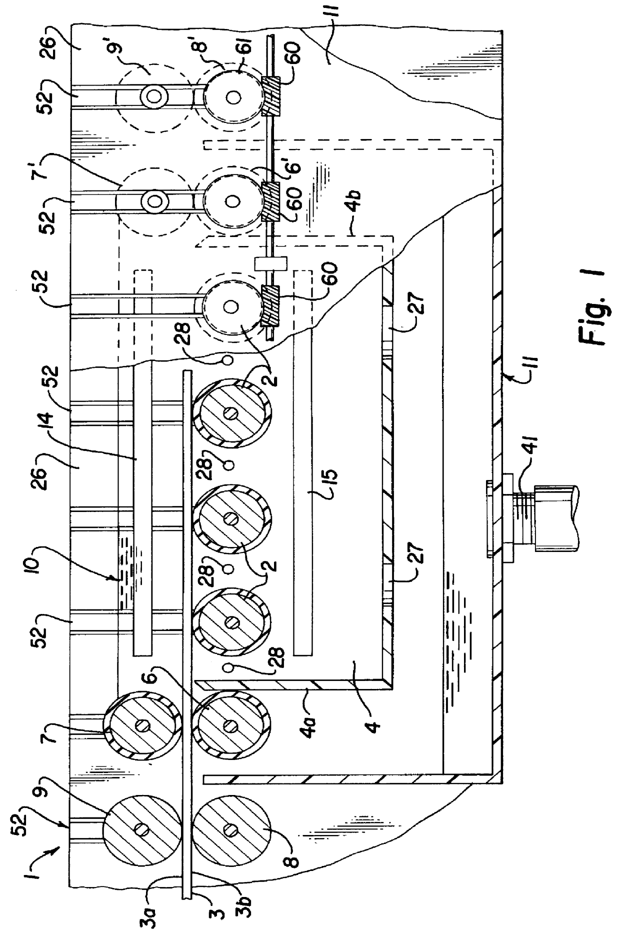
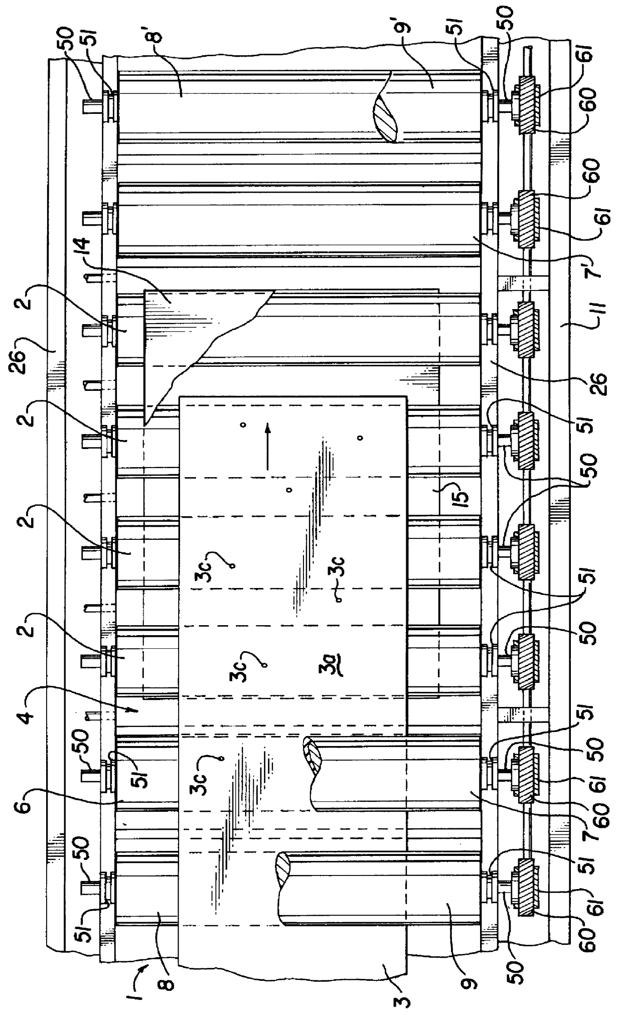
As best illustrated in FIG. 1, conveyor means such as a horizontal, driven-roller conveyor 1 with rollers arranged transverse to the direction of travel of the work pieces 3 as shown by the arrow, transports a work piece 3 horizontally through a horizontal flood plating cell means 4. Driven conveyor rollers 2 carry the work piece 3. The work piece 3 is typically a discreet, flat panel having an upper surface 3a and lower surface 3b. Often the work piece 3 will have numerous holes 3c formed therein by punching or drilling. Driven pinch rollers 6 and 6' and idler pinch rollers 7 and 7' respectively are arranged with axes aligned transverse to the path of the work piece 3 and act together to form a dam at each end 4a and 4b of the flood plating cell 4 while still allowing the work pieces 3 to pass into and out of the flood plating cell 4. The idler pinch rollers 7 and 7' are supported by suitable means in a manner as to permit rolling contact with the driven pinch rollers 6 and 6' resp...


PUM

PropertyMeasurementUnit
lengthaaaaaaaaaa
lengthsaaaaaaaaaa
widthaaaaaaaaaa

Abstract

This invention comprises a driven conveyor for transporting work pieces into one or more flood plating cells for electroplating a metal onto the planar surfaces and surfaces of the through holes of the work piece. An electrolyte solution is pumped by one or more recirculating pumps into the flood cell at such a rate as to maintain the liquid at a desired level covering the anodes and work pieces while work pieces are moved through the cells. One or more power sources provide direct current to the anodes and to the electrified contactors to transmit electrical current to the work pieces. The electrified contactors are positioned across the path of the work piece and spaced outside of the flood cell such that the electrolyte solution does not contact the contactors. Plating will occur so long as the work piece is in contact with one or more of the electrified contactors and the electrolyte.

Description

BACKGROUND OF INVENTIONThis invention is a unique arrangement of a plating device for electroplating work pieces with metallic deposits. It is often desirable to process the work pieces using conveyorized equipment. When the work pieces are flat sheets or plates with through holes, such as printed circuit boards, they are often processed through operations in which solutions are forced through the holes. Examples of this include: drilling smear removal, drilling burr residue removal, applying materials to hole walls to make nonconductive hole walls conductive, stripping of metallic deposits from hole walls, and development of coatings out of holes.The most commonly used conveyorized equipment for such applications has a horizontal roller conveyor on which the work pieces are placed. The work pieces are carried horizontally through processing chambers where solutions are pumped or sprayed onto the surfaces and into the through holes. Other less common processing equipment has a conve...

Claims


Application Information

Patent Timeline
Patent Type & Authority Patents(United States)
IPC IPC(8): C25D17/00H05K3/24C25D7/00C25D17/06C25D21/00H05K3/18
CPCC25D17/00C25D5/04C25D7/0621H05K3/241C25D7/0657C25D17/005
Inventor CONDRA, RICHARD CARROLLJOHNSON, RICHARD MALCOLM
Owner OLIVER SALES
Why Eureka
Try Eureka