Method for heating exhaust gas in a substrate reactor

a substrate reactor and exhaust gas technology, applied in the direction of chemically reactive gases, crystal growth processes, coatings, etc., can solve the problems of contaminating the wafer being processed and reducing the device yield

Inactive Publication Date: 2000-11-28
APPLIED MATERIALS INC
View PDF18 Cites 42 Cited by
  • Summary
  • Abstract
  • Description
  • Claims
  • Application Information

AI Technical Summary

Problems solved by technology

A problem with this type of processing apparatus is that some of the processing gas, which is often a gas or mixture of gases for depositing a layer of a material on the surface of the wafer, tends to flow around the edge of the susceptor and deposits a layer of the material on the back surface of the susceptor.
Unfortunately, however, as the purge gas flows from the lower portion of the chamber to the upper portion of the chamber in order to exit through the exhaust passage 116 located in the upper portion 122 of chamber 122, it carries metal contaminants from the lower portion of the chamber into the upper portion, resulting in contamination of wafers being processed.
Another problem associated with the processing apparatus of FIG. 1 is that as deposition gas 115 exits the chamber through exhaust passage 116, the deposition gas cools and condenses to form deposits 114 within the exhaust passage 116.
Deposits 114 can detrimentally affect film quality and uniformity which can result in a substantial decrease in device yield.

Method used


Image

  • Method for heating exhaust gas in a substrate reactor
  • Method for heating exhaust gas in a substrate reactor
  • Method for heating exhaust gas in a substrate reactor

Examples


Embodiment Construction

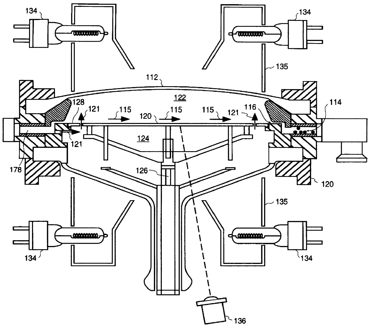
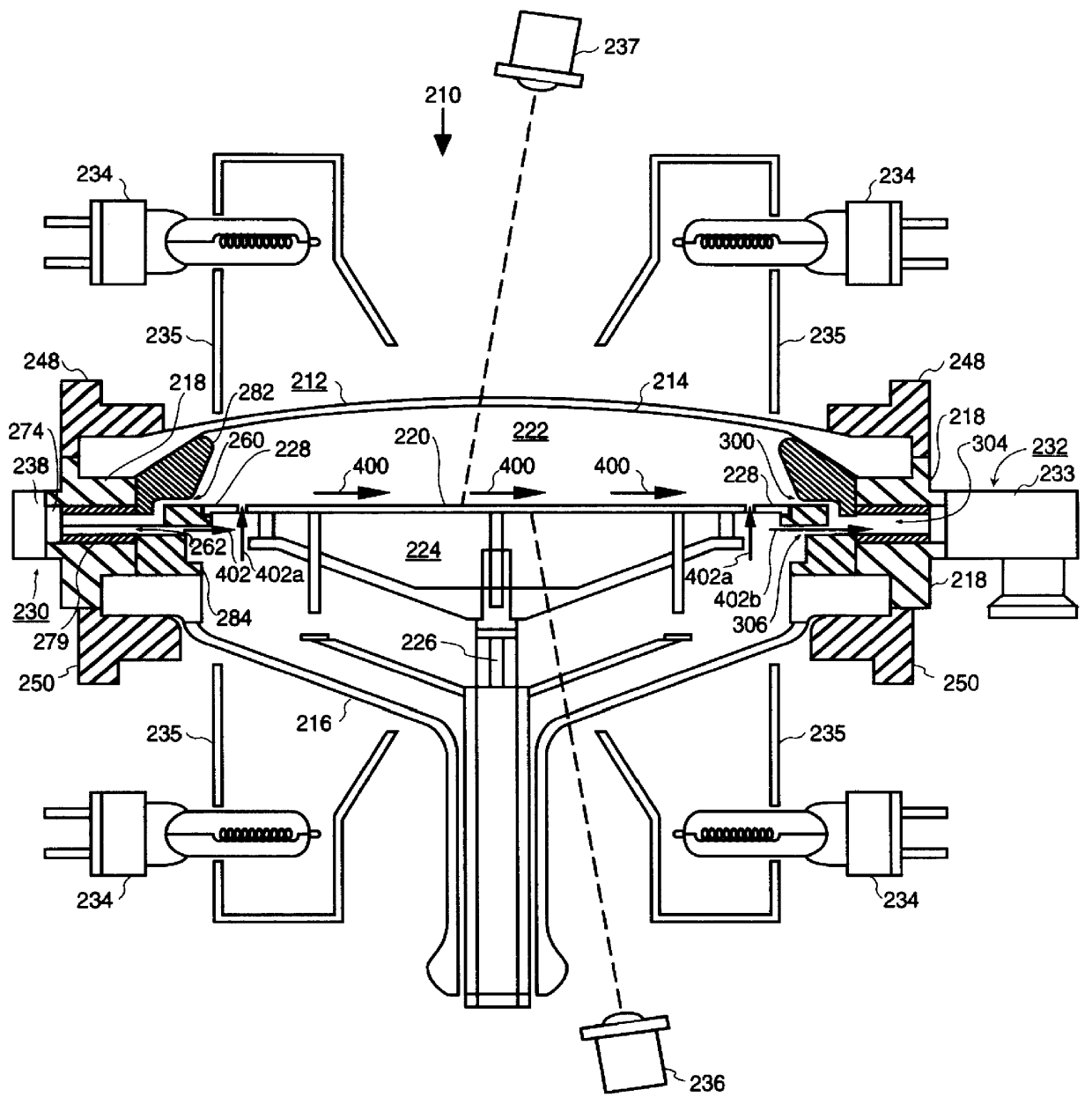
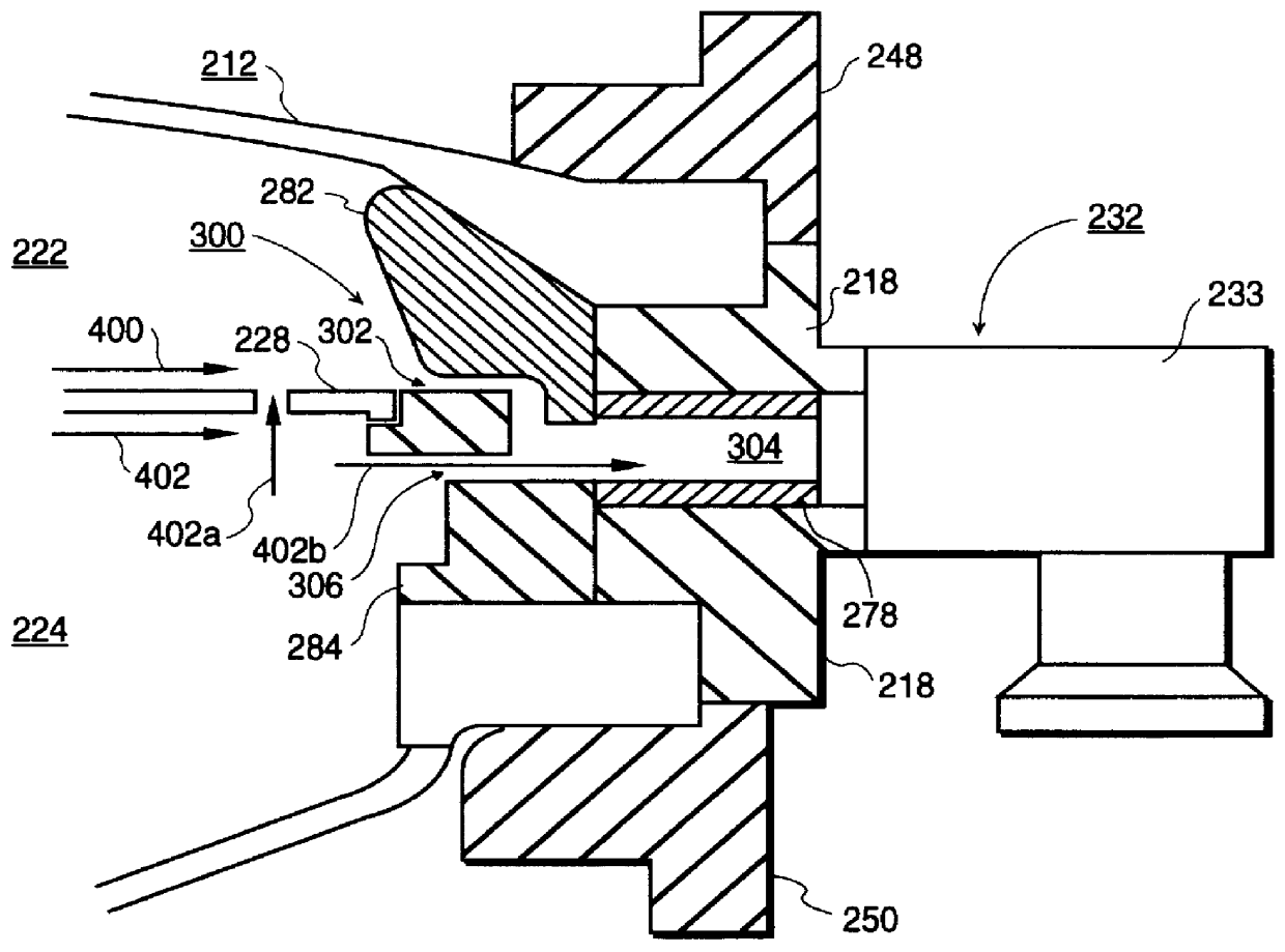
The present invention describes a method and apparatus for preventing the condensation of deposition gas in the exhaust passage of a single wafer processing reactor. In the following description numerous specific details are set forth such as specific heating elements, gases, etc., in order to provide a thorough understanding of the invention. In other instances, well known reactor features and processes have not been explained in detail in order to not unnecessarily obscure the present invention.

The present invention is a single wafer reactor. A susceptor for holding a wafer to be processed is positioned within a deposition chamber and divides the chamber into an upper portion and a lower portion. Deposition gas which feeds into the upper portion of the chamber and across the wafer is exhausted through an exhaust passage which extends from the upper portion of the chamber and out through a sidewall in the deposition chamber. An inert gas, such as H.sub.2, is fed into the lower port...


PUM

PropertyMeasurementUnit
angleaaaaaaaaaa
temperatureaaaaaaaaaa

Abstract

The present invention is a single wafer reactor having a vented lower liner for heating exhaust gas. The apparatus of the present invention includes a reaction chamber. A wafer support member which divides the chamber into an upper and lower portion is positioned within the chamber. A gas outlet for exhausting gas from the chamber has a vent to exhaust gas from the lower portion of the chamber and an exhaust passage opening to exhaust gas from the upper portion of the chamber. Heated inert purge gas is fed from the lower chamber portion through the vent at a rate so as to prevent the deposition gas from condensing in the exhaust passage.

Description

1) Field of the InventionThe present invention relates to semiconductor processing equipment, more particularly, to a method and apparatus for reducing particle contamination in a semiconductor processing apparatus.2) Discussion of Related ArtOne type of processing apparatus for semiconductor wafers is a single wafer processor in which one wafer at a time is processed in a processing chamber. An example of a single wafer reactor is shown in FIG. 1. A susceptor 120 divides a chamber 112 into one portion which is below the susceptor (the lower portion) 124, and a second portion which is above the susceptor (the upper portion) 122. The susceptor 120 is generally mounted on a shaft 126 which rotates the susceptor about its center to achieve a more uniform processing of the wafer. A flow of a processing gas, such as a deposition gas 115, is provided in the upper portion 122 of the chamber. The chamber generally has a gas inlet passage 178 at one side thereof, and a gas exhaust passage 11...

Claims


Application Information

Patent Timeline
Patent Type & Authority Patents(United States)
IPC IPC(8): C23C16/44C30B31/00C30B31/16C23C16/48C30B25/14C23C16/455H01L21/205
CPCC23C16/4408C23C16/4412C30B31/16C30B25/14C23C16/481H01L21/30
Inventor COMITA, PAUL B.CARLSON, DAVID K.RILEY, NORMA B.FAN, DORIA W.RANGANATHAN, REKHA
Owner APPLIED MATERIALS INC
Why Eureka
Try Eureka