Tap antenna unit

Inactive Publication Date: 2000-11-28
LOGITECH EURO SA
View PDF11 Cites 56 Cited by
  • Summary
  • Abstract
  • Description
  • Claims
  • Application Information

AI Technical Summary

Problems solved by technology

However, the use of a local transmitter or a loc

Method used


Image

  • Tap antenna unit
  • Tap antenna unit

Examples


Embodiment Construction

)

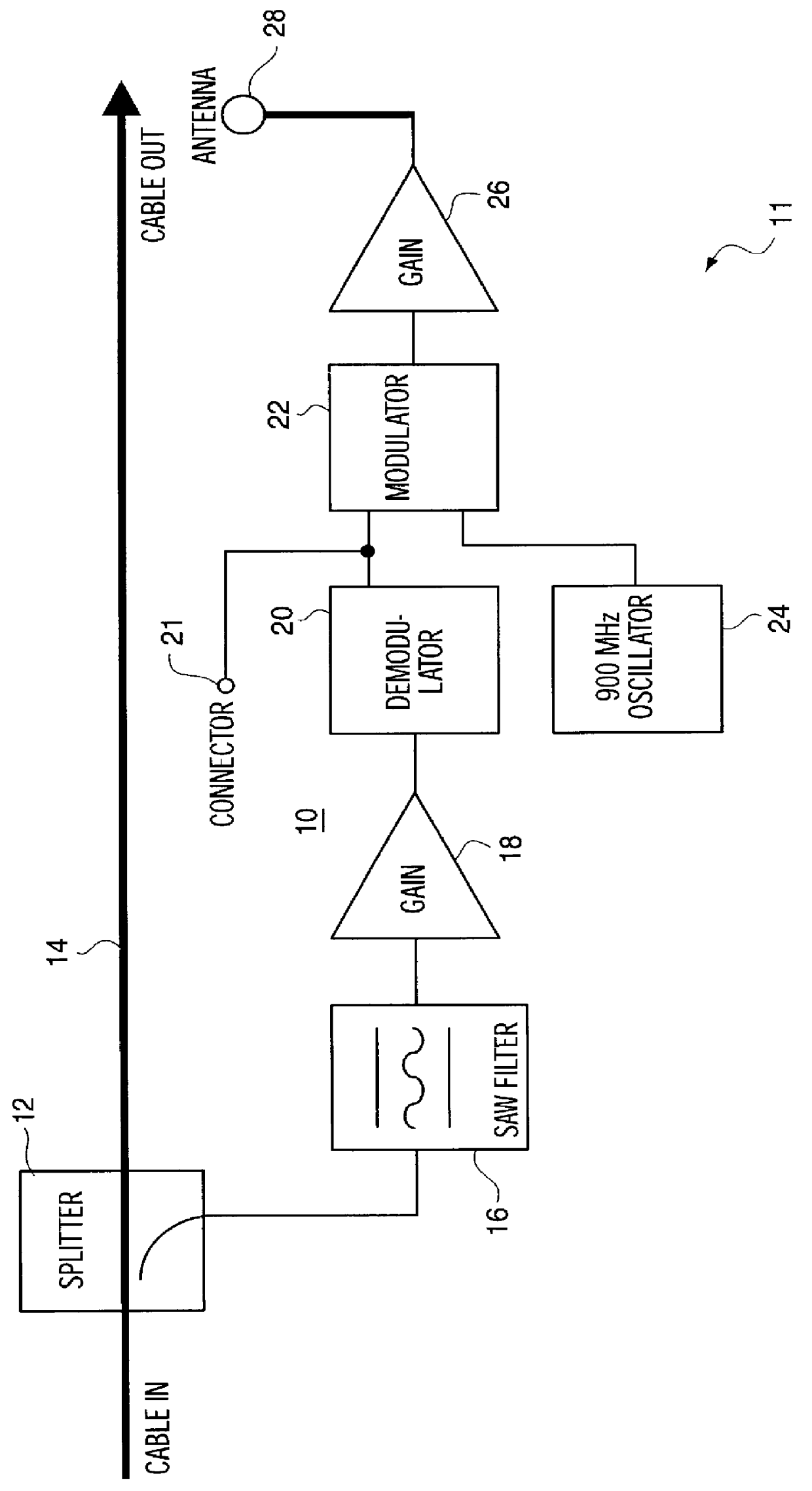
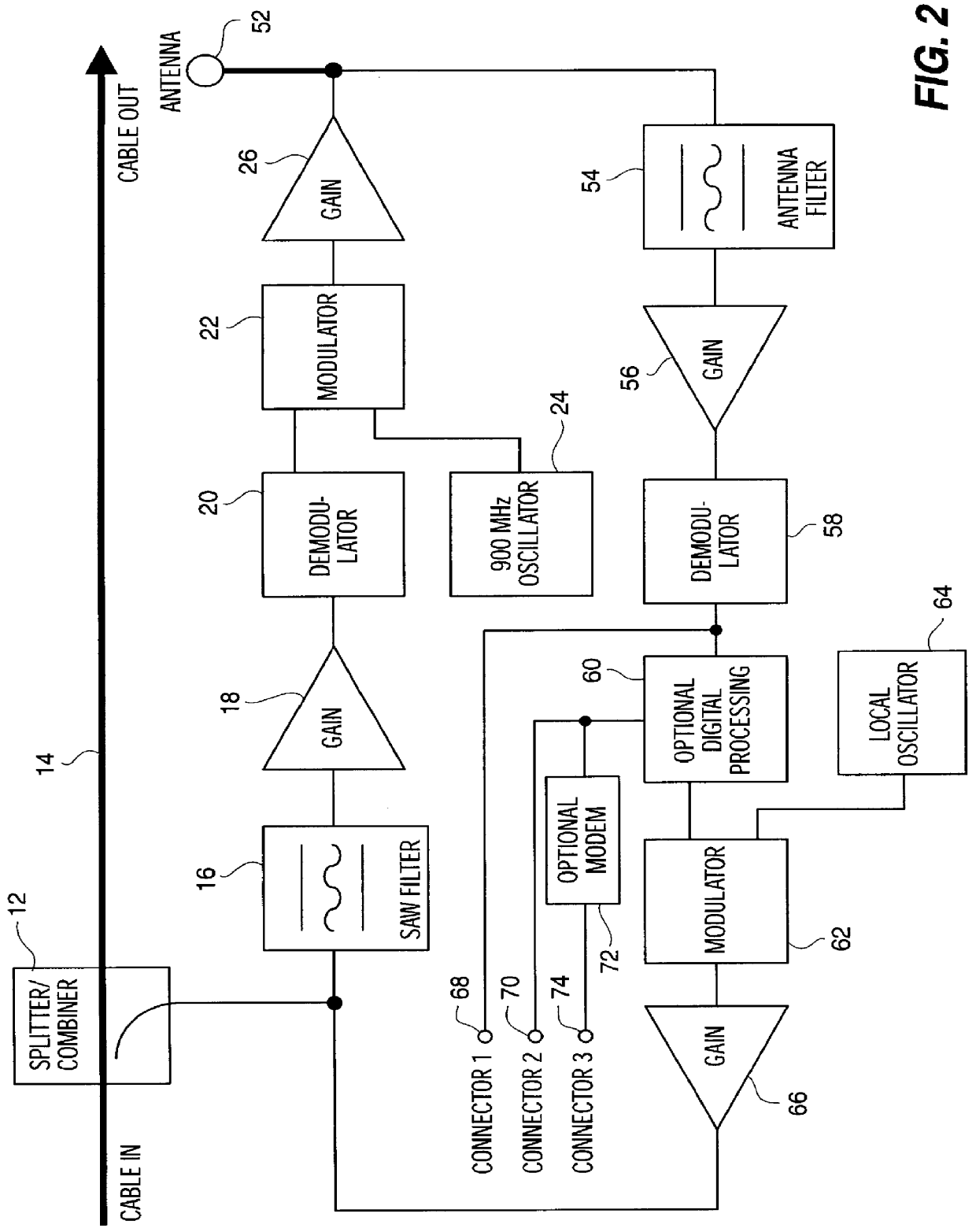
Referring to FIG. 1, the present invention relates to a tap antenna unit 10 which can be a one way system (FIG. 1), or a two way system (FIG. 2). Circuitry 11 for a one way tap antenna unit 10 is illustrated schematically in FIG. 1 and includes a wave splitter 12 connected into a coaxial cable 14 going to a consumer electronic device, such as a television set. From the splitter 12, a signal split off from the cable 14 passes through a surface acoustic wave (SAW) filter 16 and then is amplified by an amplifier 18. The output of the amplifier 18 is fed to a demodulator 20 and the demodulator output is fed to a modulator 22.

Also connected to the modulator 22 is an oscillator 24 which can output a frequency of between 902-928 MHz and which is referred to as a 900 MHz (nominal) oscillator 24. Then, the signal is amplified again by an amplifier 26 and output through an antenna 28.

The SAW filter 16 is capable of selecting a low level but sharp frequency band somewhere in the energy spectr...


PUM


Abstract

The tap antenna unit includes signal splitting circuitry, coupled to a coaxial cable which is servicing a consumer electronic device, such as a television set, for splitting off a signal from the coaxial cable; a filter coupled to an output of the signal splitting circuitry for selecting a low-level sharp frequency band in the energy spectrum of the coaxial cable; circuitry for demodulating a signal carried by the low-level frequency band; circuitry for modulating the output signal onto a carrier in an unlicensed frequency band; and an output antenna which is coupled to the modulating circuitry and which is capable of transmitting the output modulated signal over a limited transmitting-receiving area.

Description

1. Field of the InventionThe present invention relates to a tap antenna unit which includes a signal wave splitter coupled to a television coaxial cable and having an output coupled to a filter, which can be a surface acoustic wave (SAW) filter capable of selecting a low-level but sharp frequency band somewhere in the energy spectrum of TV coaxial cable, such as for example 100-200 Khz wide, 40 dB down, located between 50-800 MHz. The signal is not carried in the video signal and is AM modulated with digital data at around 10 Kb per second and such digital data is remodulated onto a carrier signal in the unlicensed ISM band at 902-928 MHz, e.g. 916 MHz, and broadcast via a self-contained antenna to a receiving unit, such as a remote control.Further, the present invention relates to a two-way tap antenna unit which can support two-way communication for devices in the home, such as a remote control, that can send 900 MHz data to the tap antenna. Such data is received by the tap antenn...

Claims


Application Information

Patent Timeline
IPC IPC(8): H04H1/02H04N7/10H04N7/173H04N5/44H04N5/775H04H20/78H04L29/08
CPCH04N7/17309H04N7/104H04H20/78H04N5/44H04N5/7755H04B1/00
Inventor THOMPSON, JOHN R.DARBEE, PAULHANAFEE, MICHAEL
Owner LOGITECH EURO SA
Why Eureka
Try Eureka