Ceramic radial flow turbine heat shield with turbine tip seal

a turbine tip and ceramic radial flow technology, applied in the field of heat shields, can solve the problems of loss of efficiency, adversely affecting engine efficiency, adversely affecting engine efficiency, etc., and achieve the effects of reducing the tip clearance, minimizing the flow, and improving the efficiency of the turbin

Inactive Publication Date: 2000-12-05
CAPSTONE TURBINE
View PDF9 Cites 29 Cited by
  • Summary
  • Abstract
  • Description
  • Claims
  • Application Information

AI Technical Summary

Benefits of technology

The present invention provides a heat shield having a peripheral ring which is spaced radially from the peripheral tip of a turbine to form a tip clearance. The turbine and heat shield have differing coefficients of thermal expansion such that the tip clearance is reduced when the engine heats up. This reduced tip clearance minimizes flow along the backface of the turbine, which improves turbine efficiency.
More specifically, the present invention provides a turbine engine including a rotatable turbine having a peripheral tip and a backface. A heat shield is positioned adjacent the backface and includes an integral ring extending from a peripheral edge of the heat shield to a position spaced radially outwardly from the peripheral tip of the rotatable turbine to form a tip clearance between the ring and the peripheral tip. The turbine comprises a material having a coefficient of thermal expansion at least approximately four times greater than the coefficient of thermal expansion of the heat shield such that the turbine expands toward the ring as a result of heat within the engine, thereby reducing the tip clearance to minimize air flow along the backface and improve efficiency of the engine.

Problems solved by technology

Also, in a high performance gas turbine engine, it is of prime importance that the heat shield maintain a minimal clearance from the turbine impeller to minimize flow of heated air behind the backface of the turbine, which adversely affects efficiency of the engine.
This spacing results in substantial airflow along the backface of the impeller, thereby adversely affecting engine efficiency.
This gap 8 allows flow of heated air along the backface 4 of the turbine 5, which causes losses in efficiency.

Method used


Image

  • Ceramic radial flow turbine heat shield with turbine tip seal
  • Ceramic radial flow turbine heat shield with turbine tip seal
  • Ceramic radial flow turbine heat shield with turbine tip seal

Examples


Embodiment Construction

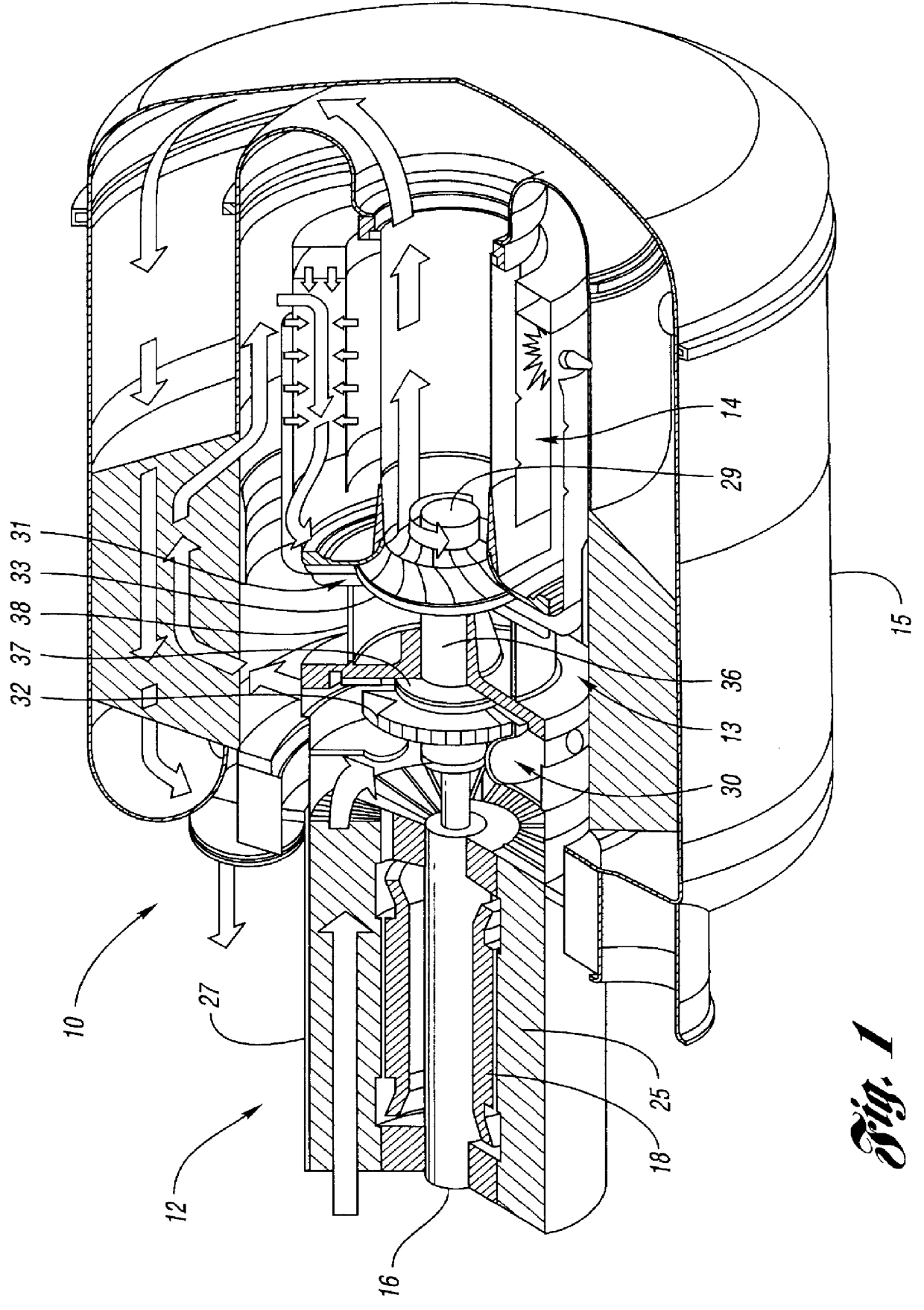
A permanent magnet turbine generator / motor 10 is illustrated in FIG. 1 as an example of a turbine engine in which the heat shield of the present invention could be implemented. The permanent magnet turbine generator / motor 10 generally comprises a permanent magnet generator 12, a power head 13, a combustor 14 and a recuperator (or heat exchanger) 15.

The permanent magnet generator 12 includes a permanent magnet rotor or sleeve 16, having a permanent magnet disposed therein, rotatably supported within a permanent magnet generator stator 18 by a pair of spaced journal bearings. Radial permanent magnet stator cooling fins 25 are enclosed in an outer cylindrical sleeve 27 to form an annular air flow passage which cools the stator 18 and thereby preheats the air passing through on its way to the power head 13.

The power head 13 of the permanent magnet turbo generator / motor 10 includes compressor 30, turbine 31, and bearing rotor 36 through which the tie rod 29 passes. The turbine 31 drives ...


PUM


Abstract

A turbine engine includes a rotatable turbine having a peripheral tip and a backface. A heat shield is positioned adjacent the backface and includes an integral ring extending from a peripheral edge of the heat shield to a position spaced radially outwardly from the peripheral tip of the rotatable turbine to form a tip clearance between the ring and the peripheral tip. The turbine comprises a material having a coefficient of thermal expansion at least approximately four times greater than the coefficient of thermal expansion of the heat shield such that the turbine expands toward the ring as a result of heat within the engine, thereby reducing the tip clearance to minimize air flow along the backface and improve efficiency of the engine.

Description

The present invention relates to a turbine engine having a turbine and a ceramic heat shield with a ring forming a tip clearance between the ring and the peripheral tip of the turbine.Modern gas turbine engines can be extremely compact, with temperature sensitive components such as turbine rotor bearings placed in close proximity to the turbine section in some designs. This has necessitated the use of shielding for protection, which shielding is positioned between the hot combustion gases and the critical components.Also, in a high performance gas turbine engine, it is of prime importance that the heat shield maintain a minimal clearance from the turbine impeller to minimize flow of heated air behind the backface of the turbine, which adversely affects efficiency of the engine. Typical flat heat shields positioned adjacent the backface of the turbine require substantial spacing from the turbine as a result of "flowering" or "bending" of the turbine tip during engine operation. Spaci...

Claims


Application Information

Patent Timeline
Patent Type & Authority Patents(United States)
IPC IPC(8): F01D11/08F01D5/02F01D11/18F01D5/04
CPCF01D5/043F01D11/18F01D5/046
Inventor ROUSE, GREGORY C.
Owner CAPSTONE TURBINE
Why Eureka
Try Eureka