Basic surge protector

Inactive Publication Date: 2000-12-05
AHUJA OM
View PDF2 Cites 64 Cited by
  • Summary
  • Abstract
  • Description
  • Claims
  • Application Information

AI Technical Summary

Problems solved by technology

Many surge and lightning protection products are currently available on the market today but none of them provide reliable surge and lightning protection above and beyond, providing one to three MOVs, and except perhaps warn you by way of a little light or a buzzer indicating that the MOV has failed, and that now you are without surge and lig

Method used


Image

  • Basic surge protector
  • Basic surge protector
  • Basic surge protector

Examples


Embodiment Construction

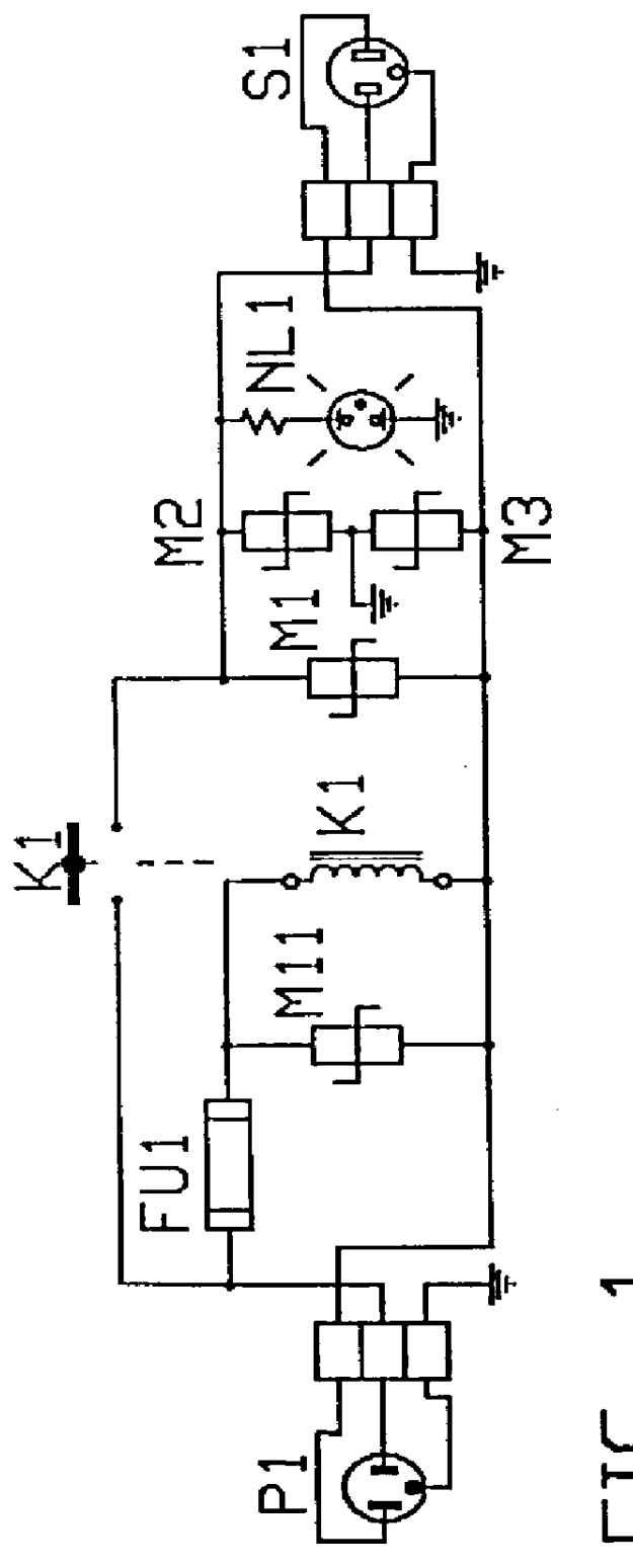
FIG. 1 illustrates the Basic Surge Protector using an elctromechanical relay K1 and MOVs M1, M2 and M3 as secondary Surge and Transient Voltage protectors. The components FU1, M11 and K1 are the key components of this invention in its very Basic form as a Basic Surge Protection. By design the breakdown voltage of the MOV M11 would be less than M1. Thus when a surge or transient voltage in excess of a predetermined value is detected by M11, it goes into heavy conduction causing the fuse F1 to blow. This disables the relay / Contactor K1 thus sparing the entire system of the potential damage that would otherwise be caused by the surge. Just by replacing the blown fuse the system would be back in operation again.

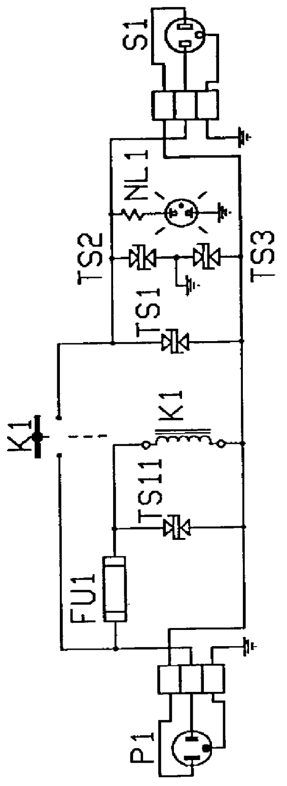
FIG. 1b illustrates the Basic Surge Protector as in FIG. 1 using Transient Voltage Suppressors. These devices provide sub-nano second response time and provide a sharper cleaner protection to the load being protected.

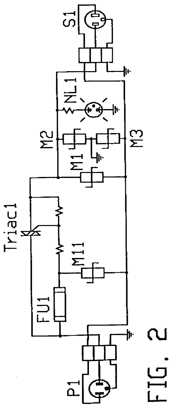
FIG. 2 illustrates the Basic Surge Protector using a Solid Stat...


PUM


Abstract

The specification discloses a Basic Surge Protector for protecting an electrical equipment connected on its load side from spurious or excessive transient voltages or surges or both on an electrical line above a predetermined value, on its line side or its hot side. Intended for use in ac circuits, dc circuits and ac/dc circuits. A fuse is used to monitor a fault current flowing into a surge voltage suppression device, due to an excessive voltage across the suppression device. Thus the fuse blows resulting from an over-current condition, and it disables and opens a solid state switch or an electro mechanical switch mounted in series in the line thus protecting the secondary or the load side from over-voltages and transient surges on the electrical line. Circuits are also disclosed which provide for automatic setting and resetting after an over-voltage fault condition on the line being protected. The lightning and surge protection as provided by this invention may also be rendered into a single chip solid state device.

Description

FIELD OF THE INVENTIONThe present invention generally relates to surge protection systems, and surge protectors for use in AC or DC circuits.BACKGROUND OF THE INVENTIONTelephone line and power line surge and lightning protection has been described in applicant's prior patents and applications as listed in the cross reference above. Additionally several single telephone line and multi party line devices have been disclosed in applicants prior patents also as listed above and as follows:U.S. Pat. No. 4,653,084 issued Mar. 24, 1987, "REMOTE ACTUATED SWITCH" (RAS) and U.S. Pat. No. 4,700,380 issued Oct. 13, 1987, "SOLID STATE REMOTE ACTUABLE SWITCH" (SSS) relate to remotely ACTUABLE solid state switches useable as solid state switches in the present invention as building blocks, for isolating and for bridging telephone lines for the purposes of routing, managing the calls and / or testing the telephone line(s).U.S. Pat. No. 4,710,949 issued Dec. 1, 1987, "TELEPHONE LINE FAULT LOCATING DEV...

Claims


Application Information

Patent Timeline
IPC IPC(8): H02H3/02H02H9/04
CPCH02H3/025H02H9/042
Inventor AHUJA, OM
Owner AHUJA OM
Why Eureka
Try Eureka