Barrier fluid seal, reciprocating pump and operating method

a reciprocating pump and fluid seal technology, applied in the direction of positive displacement liquid engines, piston pumps, machines/engines, etc., can solve the problems of premature failure of seals, leakage past the seals, pollution source,

Inactive Publication Date: 2000-12-12
TEXAS PRESSURE SYST
View PDF21 Cites 43 Cited by
  • Summary
  • Abstract
  • Description
  • Claims
  • Application Information

AI Technical Summary

Problems solved by technology

Reciprocating pumps used in high-pressure applications, such as for chemical injection into a high-pressure vessel, have seals for containing a process fluid to be pumped, but it has been common to have some leakage past the seals.
Such leakage is wasteful, and it leads to premature failure of the seals as well as being a source of pollution.
However, a reciprocating rod, pump or compressor does not have a rotary drive shaft for circulating barrier fluid.
A further problem with a reciprocating pump is that the discharge pressure spikes upward as the pump discharges process fluid and then falls off as a plunger within the pump retracts to repeat the pumping cycle.
Unsteady cyclic pressure and flow adversely impacts process operations.
However, in some applications, such as very high-pressure chemical injection, such pressure surges are undesirable.

Method used


Image

  • Barrier fluid seal, reciprocating pump and operating method
  • Barrier fluid seal, reciprocating pump and operating method
  • Barrier fluid seal, reciprocating pump and operating method

Examples


Embodiment Construction

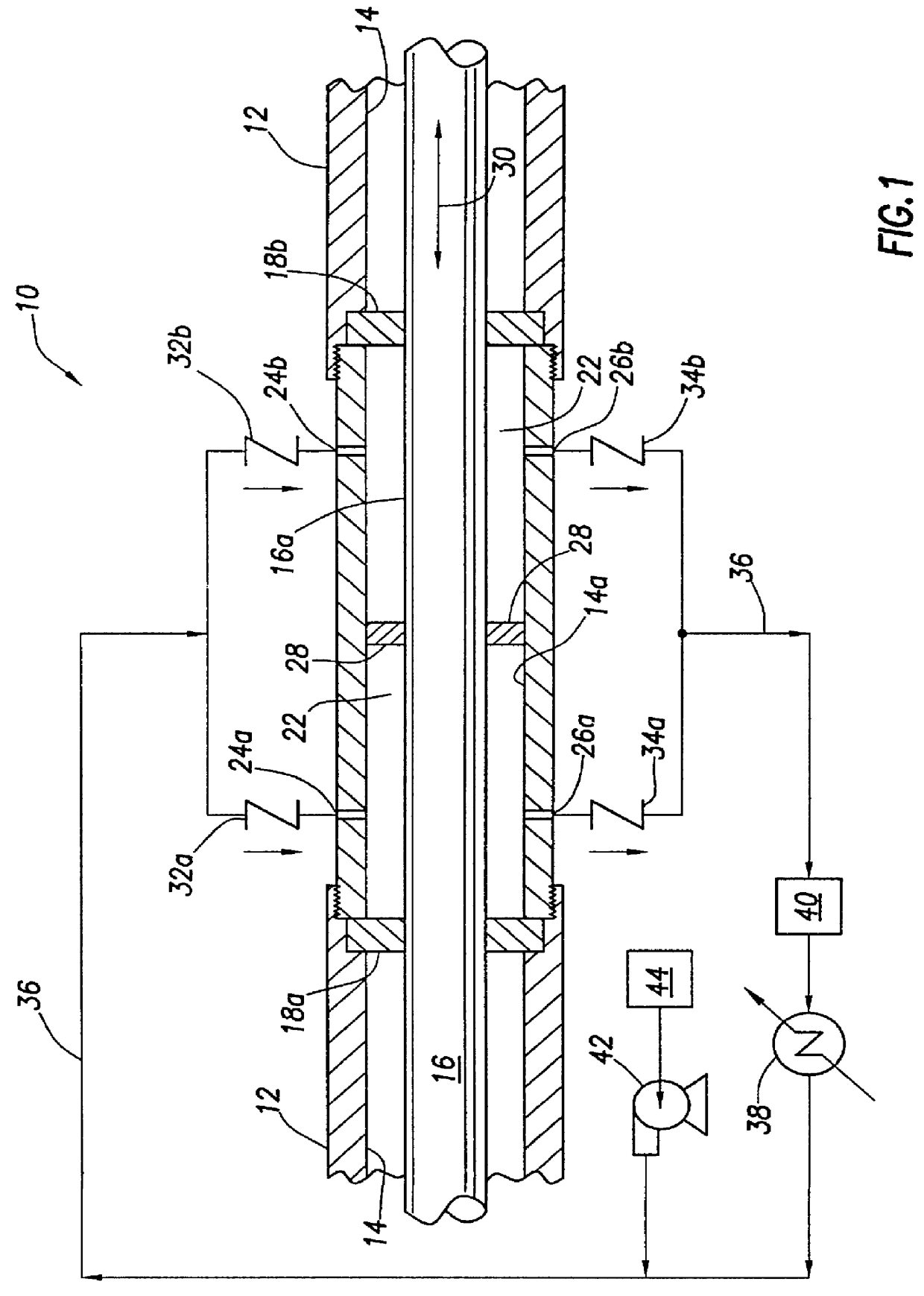
With reference to FIG. 1, a barrier fluid seal assembly 10 is illustrated in cross section. A body 12 has a bore 14, and a rod 16 is received in bore 14. A first seal 18a and a second seal 18b provide a seal around rod 16 within bore 14. A barrier fluid chamber 22 is defined within bore 14 between seals 18a and 18b as an annular space around rod 16. Body 12 has first and second inlet ports 24a and 24b, respectively, providing ingress openings for receiving a process-compatible barrier fluid into chamber 22. Body 12 also has first and second outlet ports 26a and 26b, respectively, providing egress openings through which the barrier fluid can discharge from chamber 22.

A pumping device 28 is mounted to rod 16 for pumping the barrier fluid within chamber 22. In this embodiment rod 16 moves back and forth as indicated by arrow 30, and pumping device 28 is a ring or flange sealingly fixed about the circumference of rod 16. Body 12 and bore 14 are cylindrical in shape, and bore 14 is defin...


PUM


Abstract

A barrier fluid seal assembly is provided for a reciprocating rod, where the reciprocation of the rod is used to pump barrier fluid through a barrier fluid chamber. The rod has first and second seals, and the barrier fluid chamber is located between the seals. Barrier fluid pressure is maintained higher than process fluid pressure so that if there is leakage past the seals, then it is barrier fluid that leaks, which keeps the seals clean and flushed. A reciprocating pump may incorporate the barrier fluid seal assembly for sealing around a plunger. A method of operating first and second reciprocating pumping cylinders provides bumpless transfer of pumping from one pumping cylinder to the other pumping cylinder. Motion controls, such as a controller using a position transducer for a hydraulic piston and a servo-valve for providing hydraulic fluid to the hydraulic piston, are used to compress liquid process fluid in one pumping cylinder prior to beginning its pumping stroke. A total plunger speed is determined for plungers in pumping cylinders A and B, and total plunger speed is held essentially constant prior to hand-off of pumping from one pumping cylinder to another pumping cylinder. The speed of one plunger is increased before it enters its pumping stroke while the speed of the other plunger is decreased an equal amount as it reaches the end of its pumping stroke.

Description

Not applicable.1. Field of the InventionThis invention pertains to barrier fluid seals, pumps and compressors, and more particularly to a barrier fluid seal assembly for a reciprocating rod, a reciprocating pump with the seal assembly and a method for operating reciprocating pumps.2. Description of the Related ArtMoving shafts, such as reciprocating rods, frequently require a seal around the shaft. For example, reciprocating, plunger-type pumps and compressors require a seal around the plunger. Reciprocating pumps used in high-pressure applications, such as for chemical injection into a high-pressure vessel, have seals for containing a process fluid to be pumped, but it has been common to have some leakage past the seals. Such leakage is wasteful, and it leads to premature failure of the seals as well as being a source of pollution.U.S. Pat. No. 5,746,435, issued to Arbuckle, discloses a dual seal barrier fluid leakage control method for a rotary pump. Arbuckle discloses a method fo...

Claims


Application Information

Patent Timeline
Patent Type & Authority Patents(United States)
IPC IPC(8): F04B9/00F04B9/137F04B9/105
CPCF04B9/1372F04B9/105
Inventor DUPRE, MILBURN EMILE
Owner TEXAS PRESSURE SYST
Why Eureka
Try Eureka