Method and apparatus for determining the state of fouling/cleaning of membrane modules

a technology for cleaning and membrane modules, applied in the direction of filtration separation, separation processes, instruments, etc., can solve the problems of unsuitable techniques, hinder the development of strategies to improve resistance to fouling, and the flow rate measurement does not provide a determination of when a membrane is fouling/cleaning

Inactive Publication Date: 2000-12-19
UNIV TECH
View PDF4 Cites 109 Cited by
  • Summary
  • Abstract
  • Description
  • Claims
  • Application Information

AI Technical Summary

Problems solved by technology

The lack of suitable techniques for studying membrane fouling under realistic operating conditions has hindered the development of strategies to improve resistance to fouling.
Moreover, although a decline in the permeate flow rate (i.e., the treated liquid flow rate) can be used to infer that membrane fouling is occurring, or has occurred, flow rate measurement does not provide a determination of when a membrane module has been adequately cleaned via chemical means, back flushing, or any other cleaning means, since permeation flow does not occur during membrane cleaning, and flow rate measurements are not made during cleaning.
This procedure is not practical in commercial high-pressure membrane modules.
That is, interior membrane portions cannot be seen via an optical probe.
Membrane fouling is known to cause a decline in the permeate flow rate.
However, permeate flow rates can decline for reasons other than membrane fouling.
Moreover, permeate flow rate measurements cannot be used to assess the effectiveness of cleaning fouled membrane surfaces, since no...

Method used


Image

  • Method and apparatus for determining the state of fouling/cleaning of membrane modules
  • Method and apparatus for determining the state of fouling/cleaning of membrane modules
  • Method and apparatus for determining the state of fouling/cleaning of membrane modules

Examples


Embodiment Construction

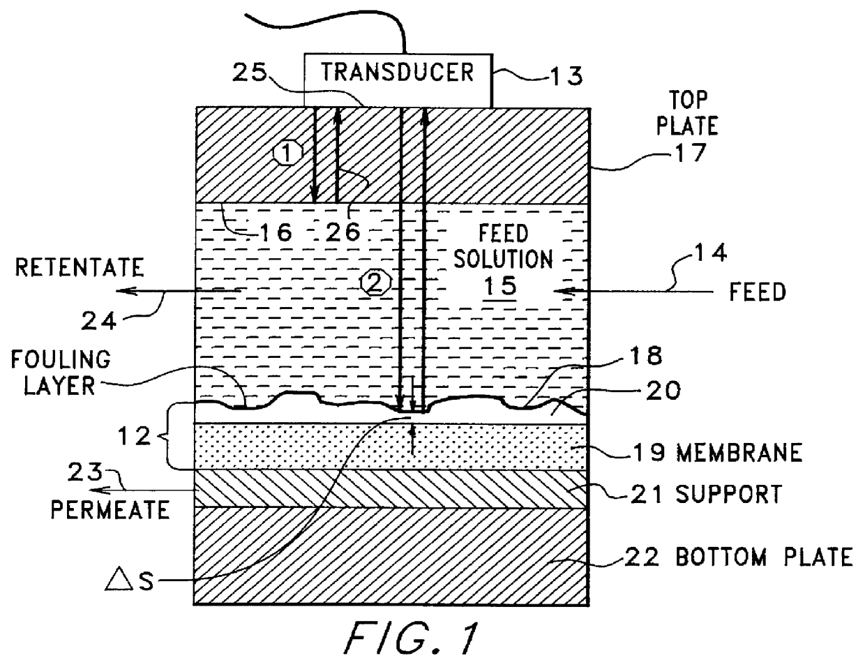
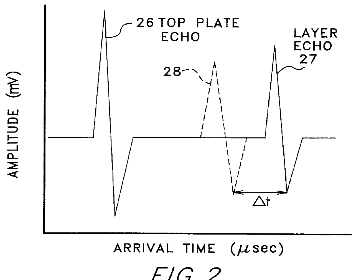
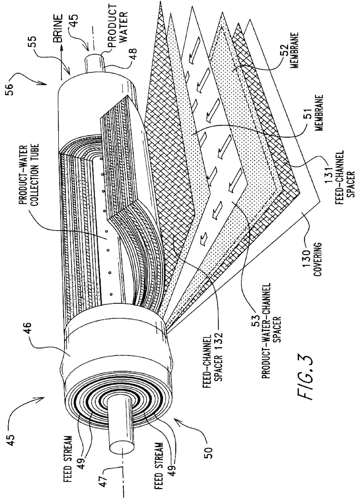
One aspect of the present invention provides an apparatus / method for measuring the fouling of pressure driven membrane modules; for example, membrane modules that contain either a spiral-wound membrane or a plurality of hollow fiber membranes. The invention provides for a measurement of the buildup of particulates and / or precipitates on a membrane that is contained within the housing of a membrane module. In a new and unusual manner, this invention employs an ultrasonic measurement system that employs high frequency sound waves to detect the presence of membrane fouling / cleaning in a noninvasive and real-time manner.

The invention employs either a single ultrasonic transducer, two ultrasonic transducers, or an array of ultrasonic transducers, to obtain data about the localized state of fouling / cleaning that exists at a location(s) that is buried within the bulk of the membrane that is contained within the membrane module's housing.

The ultrasonic transducer preferably comprises a focu...


PUM

PropertyMeasurementUnit
Diameteraaaaaaaaaa
Diameteraaaaaaaaaa
Frequencyaaaaaaaaaa

Abstract

The fouling state of a polymeric membrane within the high pressure housing of a spiral wound or a hollow fiber membrane module is determined. An ultra sonic transducer positioned with its emitting face in physical engagement with the outer surface of the housing is pulse energized by a pulser/receiver device. A membrane echo signal is detected by a receiver of the pulser/receiver device. A reference echo signal indicative of a fouled or an unfouled state of the membrane is compared to the echo signal to determine the membrane fouling state. The echo to reference comparing step can be based upon comparing amplitude domain signals, comparing time-domain signals, comparing combinations of amplitude domain and time-domain signals, and comparing transformations of amplitude domain and time-domain signals. A clean or a fouled reference echo can be provided from a clean or a fouled membrane and then stored for use during a liquid separation process, or a clean reference echo signal can be obtained on-line from a second transducer whose echo signal is derived from an area of the membrane known to remain relatively unfouled during the liquid separation process, or a clean or fouled reference echo signal can be provided for later use during a cleaning process or during a liquid separation process. Multiple transducers and a switching network can sample the fouling state at different positions within the membrane module.

Description

1. Field of the InventionThis invention relates to the field of liquid separation processes that use membrane systems, and more specifically, to methods and apparatus for determining the state of fouling and / or the state of cleaning of such membrane systems.2. Description of Related ArtIt is known that ultrasonic transducers can be used with ultrasonic pulser / receiver equipment to provide a wide variety of ultrasonic test systems, with emphasis on high-frequency applications, examples being high-resolution flaw detection, thin material thickness gaging, medical research, and materials characterization to measure sound velocity and attenuation, which in turn can be correlated to elastic modulus or grain orientation (size / texture).The use of membranes in water treatment applications is known, and a joint NWRI / NSF workshop panel has recognized the importance of detecting and monitoring the fouling process with the development of non-destructive, on-line, real-time observation technique...

Claims


Application Information

Patent Timeline
IPC IPC(8): B01D61/22B01D61/12B01D65/10B01D65/02B01D61/02B01D65/00G01N29/02G01N29/032G01N29/44G01N29/30G01N29/22G01N29/48G01N29/07G01N29/11
CPCB01D61/12B01D65/02B01D65/10G01N29/032G01N29/07G01N29/11G01N29/221G01N29/222G01N29/30G01N29/4427G01N29/4436G01N29/48B01D61/22G01N2291/044B01D2321/00G01N2291/0231G01N2291/0237G01N2291/02416G01N2291/0251
Inventor BOND, LEONARD J.CHAI, GUO YONGGREENBERG, ALAN RICHARDKRANTZ, WILLIAM BERNARD
Owner UNIV TECH
Why Eureka
Try Eureka