

Apparatus and methods for control of body lumens
- Summary
- Abstract
- Description
- Claims
- Application Information
AI Technical Summary
Benefits of technology
Problems solved by technology
Method used
Image

Examples
Embodiment Construction
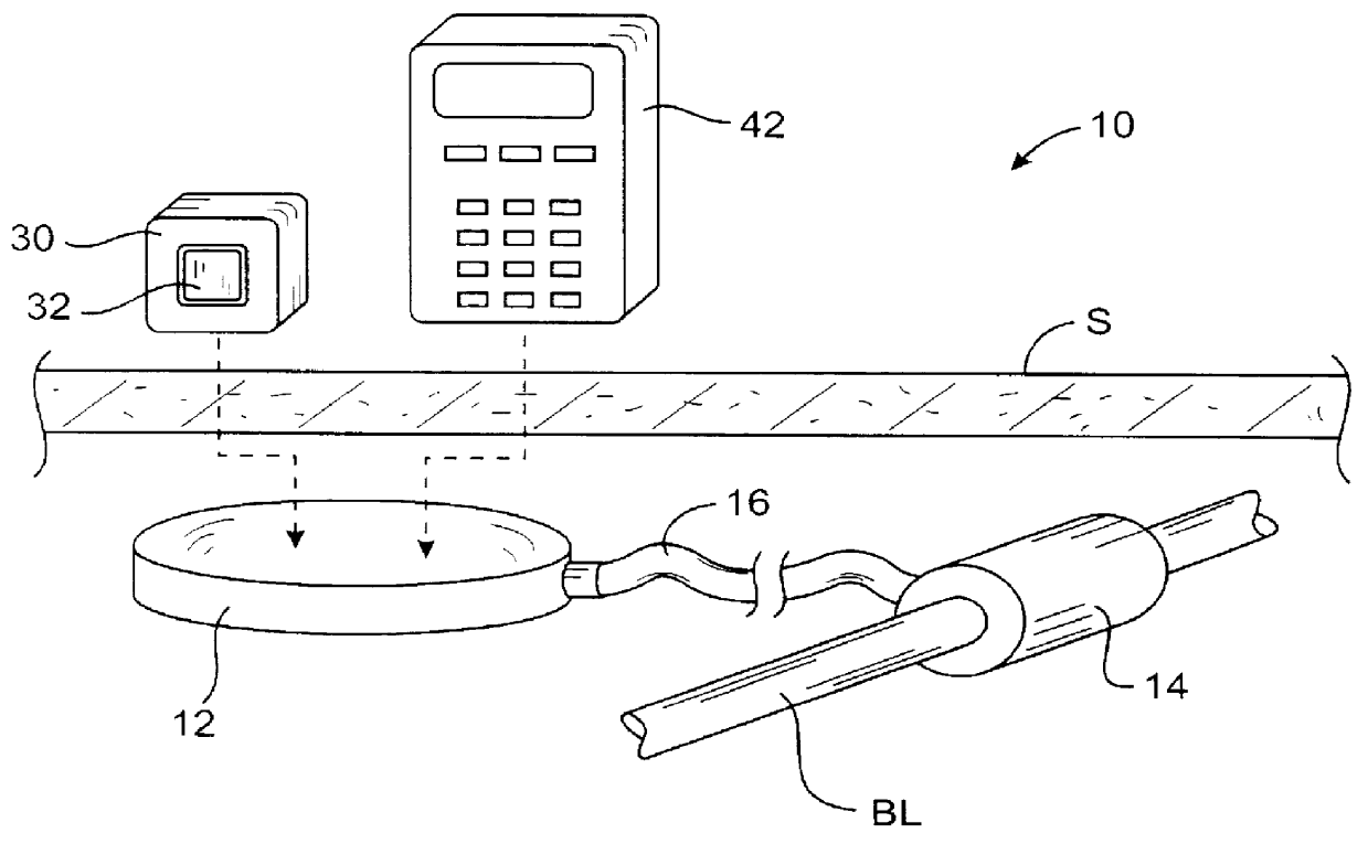
Referring to FIG. 1, systems can according to the present invention comprise at least a control module 12 and an actuator 14 which are implantable beneath the skin S of a patient by conventional surgical techniques. Usually, the control module 12 and actuator 14 will be separate components and will be implanted at separate locations, but in some instances both such components will be combined integrally in a single housing for implantation at a single site. When separate, the actuator 14 will be implanted at least partially over a target body lumen BL, typically the urethra, the rectal sphincter, the lower esophageal sphincter, the ampulla of vater, fallopian tube, vas deferens, or the like. The control module 12 will be implanted at a location remote from the body lumen, typically within a subcutaneous space (relatively close to the skin surface), typically within 0.5 cm to 10 cm of the skin surface. The actuator 14 and control module 12 will usually be implanted in separate surgic...
PUM
 Abstract
Description
Claims
Application Information