High speed frequency divider circuit

a frequency divider and high-speed technology, applied in the field of frequency divider circuits, can solve the problems of limited speed of operation, circuit outputs cannot adequately track or be generated in real time at high clock frequencies, and operating frequency limitations

Inactive Publication Date: 2000-12-26
LUCENT TECH INC
View PDF3 Cites 65 Cited by
  • Summary
  • Abstract
  • Description
  • Claims
  • Application Information

AI Technical Summary

Problems solved by technology

The problem with circuit 5 is that the speed of operation is limited and, thus, the circuit outputs cannot adequately track or be generated in real time at high clock frequencies.
Another problem resulting in operating frequency limitations is the dependency of the change of

Method used


Image

  • High speed frequency divider circuit
  • High speed frequency divider circuit

Examples


Embodiment Construction

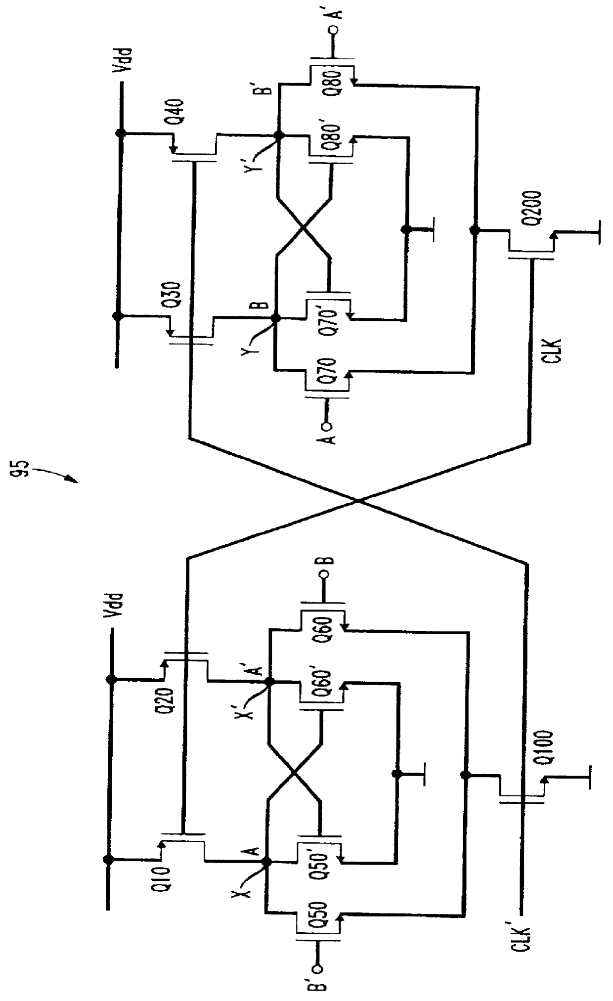
A frequency divider circuit 95 in accordance with a preferred embodiment of the present invention is depicted in FIG. 2 and includes a first circuit section 100 and a second circuit section 200. The circuit sections, like the circuit sections 10 and 20 of the prior art arrangement of FIG. 1, are substantially identical to each other and function in a cooperative relationship wherein each section generates output signals for driving the other.

With specific reference to circuit section 100, this section receives four input signals, namely, a clock signal CLK having a frequency value, an input signal "B", a complement of the input signal B, shown as B' and a complement of the clock signal, CLK'. A pair of CMOS transistors Q10 and Q20, which are preferably P-channel transistors, are connected to a DC voltage source V.sub.dd and receive the clock signal as an input at their gate terminals. As is known in the art, when CLK is "high" or at a logic "1", transistors Q10 and Q20 will remain "...


PUM


Abstract

A high frequency divider circuit for producing output signals of half the frequency of an input clock signal includes two identical circuit sections, each producing an output signal and its complement. The circuit sections are connected to each other so that the output signals of one circuit section serve as input signals to the other circuit section. Each circuit section contains a load transistor which is controlled by one of the clock signal and the clock signal complement, and a switch transistor which is controlled by the other of the clock signal and the clock signal complement. The inventive circuit exhibits a reduced RC time constant for each circuit section and an increased output signal swing between the output signals and their respective complements, as contrasted with prior art frequency dividers, thereby increasing the overall circuit response time and its ability to operate at high frequencies.

Description

1. Field of the InventionThe present invention relates to a frequency divider circuit, and more particularly to a frequency divider circuit capable of operating at high frequencies.2. Description of the Related ArtKnown frequency divider circuits operate in a master-slave flip-flop configuration of interconnected first and second sections which receive a clock signal having a frequency as an input and which output a signal having a frequency value substantially half of the clock frequency. The master-slave operation of such known circuits is achieved through feedback of the output signal of one circuit block as an additional input signal to the other circuit block and vice versa, i.e. as an input signal other than the clock signal.A known frequency divider circuit 5 is shown in FIG. 1 and includes a first circuit section 10 and a second circuit section 20. (Connections between the two circuit portions 10 and 20 are omitted for ease of illustration.) Each circuit section has a pair o...

Claims


Application Information

Patent Timeline
IPC IPC(8): H03K3/3562H03K3/00H03K3/356H03K23/44H03K23/00
CPCH03K3/356139H03K23/44H03K3/35625
Inventor WANG, HONGMO
Owner LUCENT TECH INC
Why Eureka
Try Eureka