Reduced common voltage in a DC matrix converter

a common mode and converter technology, applied in the direction of dc motor speed/torque control, control system, electric motor control, etc., can solve the problems of converter control and output voltage synthesis, and achieve the effect of reducing the size of magnetic components and reducing the output voltage of common mod

Inactive Publication Date: 2000-12-26
SUBAIR +1
View PDF1 Cites 64 Cited by
  • Summary
  • Abstract
  • Description
  • Claims
  • Application Information

AI Technical Summary

Benefits of technology

Objects of the invention include reducing the common mode output voltage of a DC matrix converter, whereby to

Problems solved by technology

The problem lies in the control of the conve

Method used


Image

  • Reduced common voltage in a DC matrix converter
  • Reduced common voltage in a DC matrix converter
  • Reduced common voltage in a DC matrix converter

Examples


Embodiment Construction

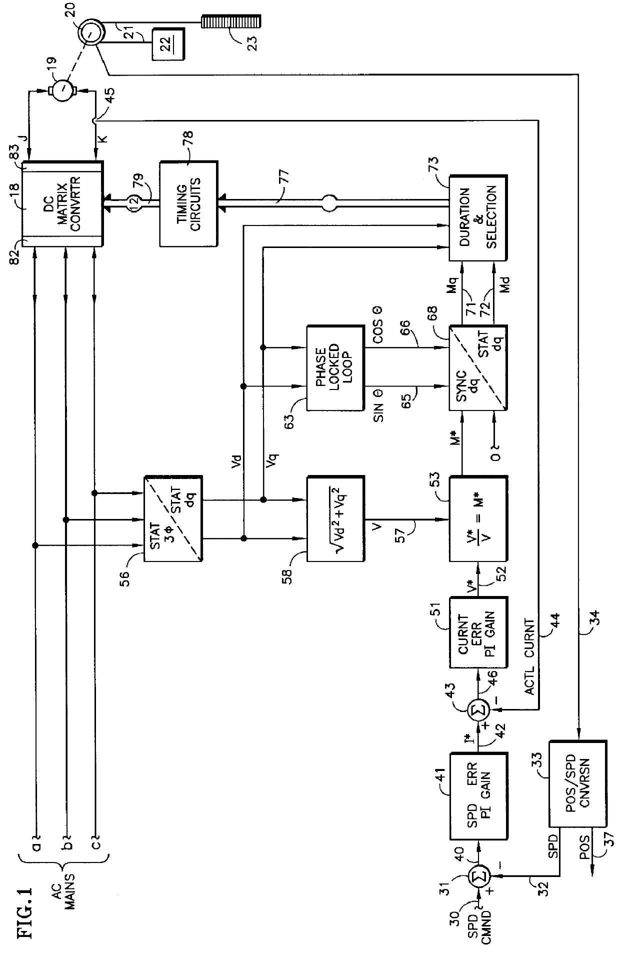
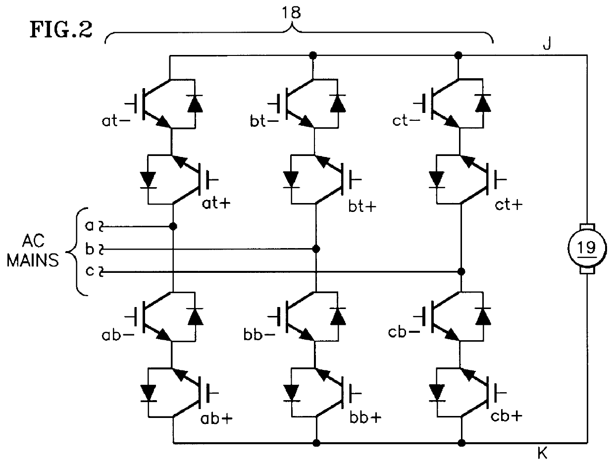
Referring to FIG. 1, a DC matrix converter 18 provides current to a DC motor 19, which in this embodiment is shown mechanically connected to a sheave 20 which is connected by roping 21 to an elevator car 22 and a counterbalance 23. The DC matrix converter 18 selectively connects various pairs of the three-phase AC mains a, b, c directly to the output terminals of the converter j, k. The voltage can be positive at terminal j and negative at terminal k, and conventional positive current flowing from terminal j to terminal k, such as, for instance, when the elevator is being driven upwardly with a heavy load, or terminal k can be positive, terminal j negative and conventional positive current flowing from k to j, such as, for instance, when the elevator is being driven downwardly with a light load; this is called "motoring". Whenever the elevator is traveling upwardly with a light load, downwardly with a heavy load, or is decelerating, the sheave 20 will actually drive the motor 19 so ...


PUM


Abstract

A DC matrix converter having six forward current conducting power switches and six reverse current conducting power switches has the on time duration of each power switch within each pulse width modulation period controlled by relationships between d, q components of a modulation index determined by the ratio of a voltage command to the instantaneous voltage of the AC mains expressed in stationary d, q coordinates, the selection of which is made based on inequalities between the AC mains voltage components expressed in dq coordinates, and relationships of the AC main voltage components expressed in d, q coordinates. Zero vectors are related to the one AC main having lower line-to-neutral voltage than the other AC mains, using relationships between the instantaneous AC mains voltage in d, q coordinates.

Description

This invention relates to reducing common mode voltage in the output of a direct, AC to DC matrix converter which supplies controlled DC voltage to a load utilizing precisely controlled, pulse width modulation.The DC matrix converter is a fully regenerative converter that directly converts three-phase AC voltage to a controlled DC output voltage without a DC bus capacitor bank. The problem lies in the control of the converter and the synthesis of the output voltage. Recent efforts have focused on the minimization of commutation losses in the converter's switching elements to increase converter efficiency. The strategy is to synthesize converter output voltage with a minimum number of commutations, based on an analytical tool commonly referred to as "space-vector" analysis. A recent control strategy for the DC matrix converter based upon this approach is disclosed and claimed in commonly-owned, copending U.S. patent application Ser. No. 09 / 310,393 filed contemporaneously herewith.In ...

Claims


Application Information

Patent Timeline
IPC IPC(8): H02M5/27H02P29/00H02M7/219H02M5/02H02P7/18H02P7/28
CPCH02M5/271H02M7/219H02P29/0038H02P7/2815H02M2007/53876H02P29/50H02M7/53876
Inventor CZERWINSKI, CHRISTOPHER S.
Owner SUBAIR
Why Eureka
Try Eureka