Display apparatus and method for driving the display apparatus
a technology of display apparatus and display device, which is applied in the direction of instruments, television systems, static indicating devices, etc., can solve the problems of increasing the electric power consumption of drain drivers, and consuming a large amount of cmos
- Summary
- Abstract
- Description
- Claims
- Application Information
AI Technical Summary
Problems solved by technology
Method used
Image
Examples
first embodiment
This embodiment represents a liquid crystal display (LCD) apparatus employing the present invention, which includes a monochrome monitor which displays data in only black and white.
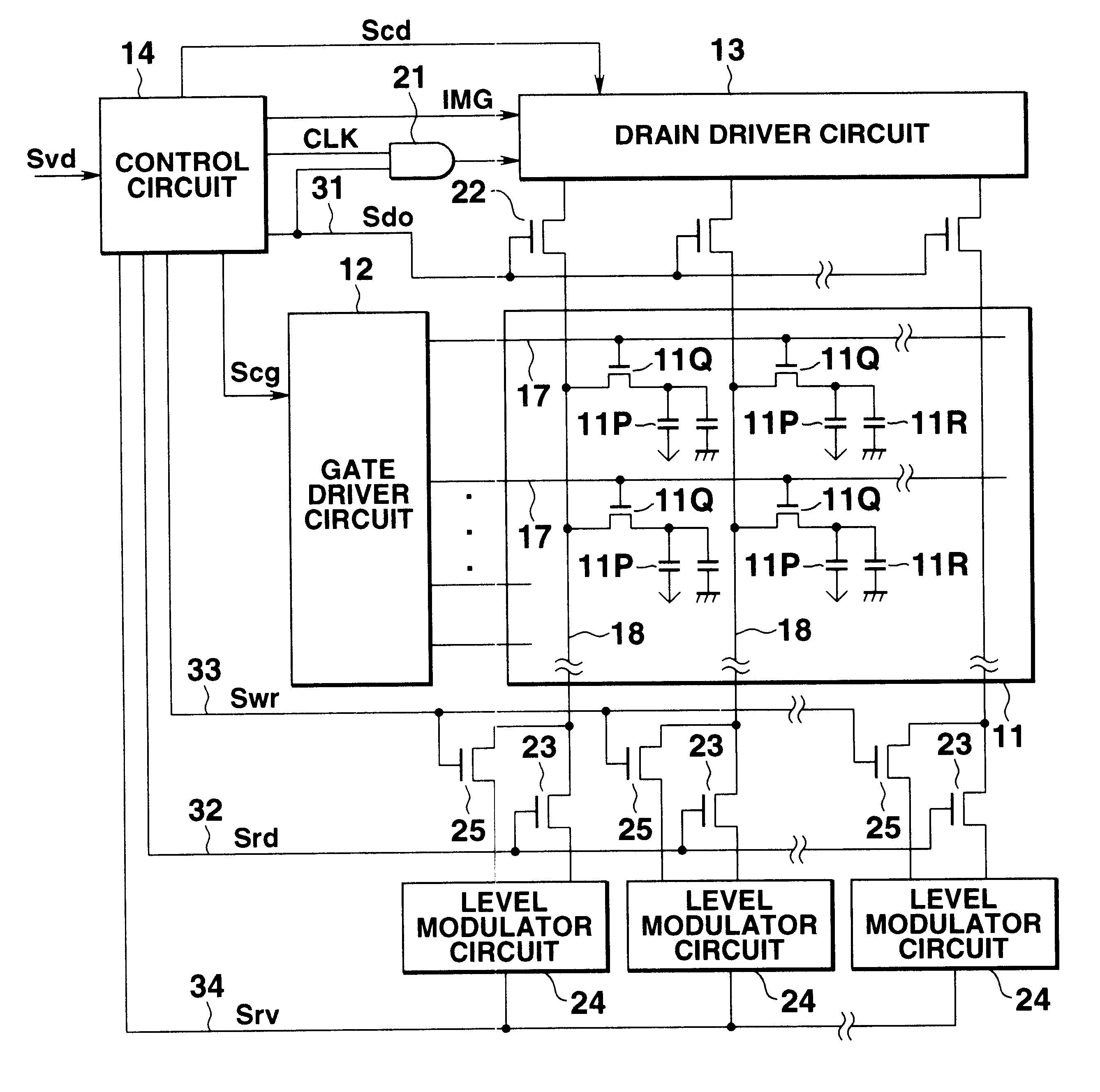
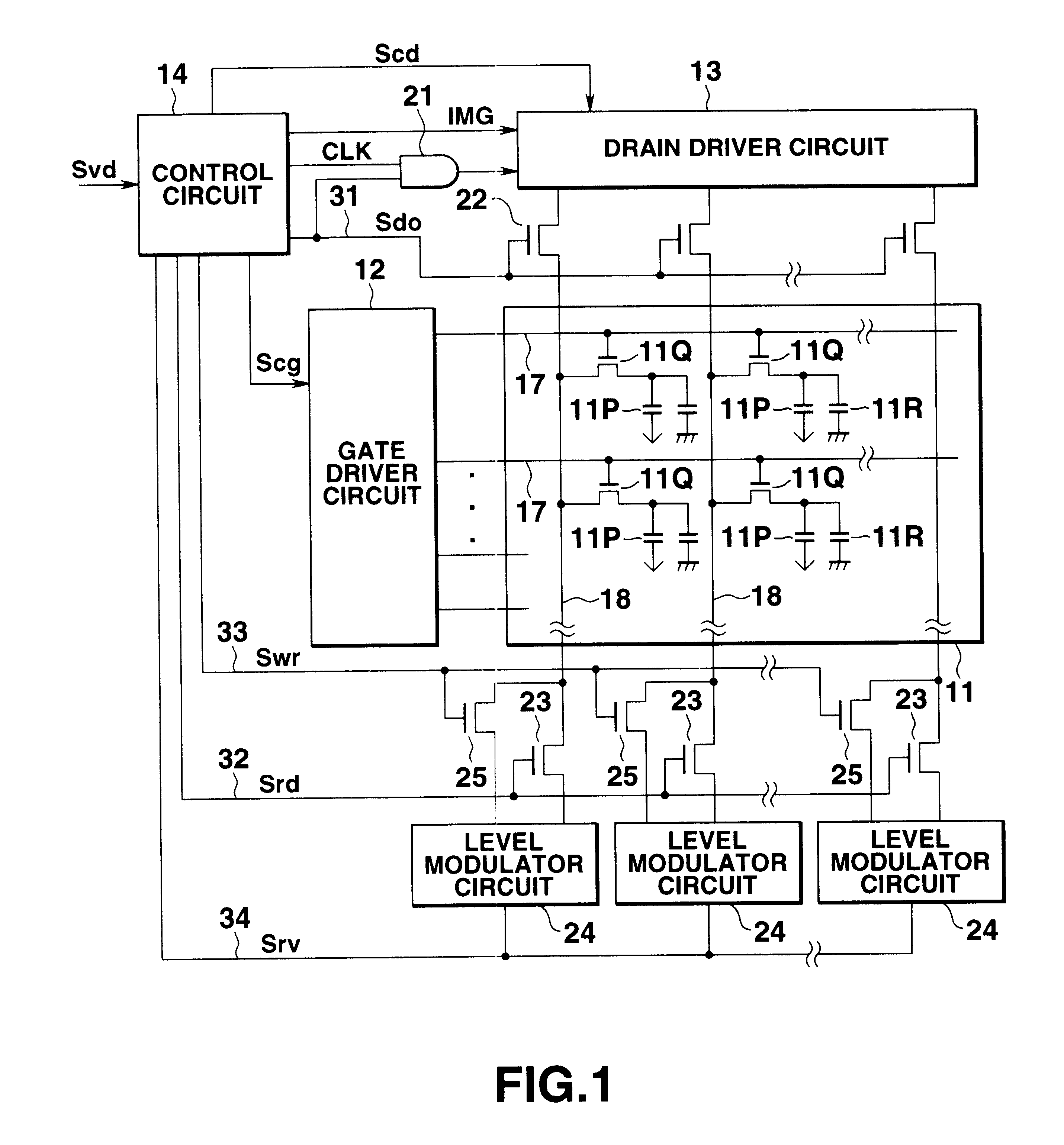
FIG. 1 is a schematic representation of the LCD apparatus of the first embodiment. The LCD apparatus comprises an LCD panel 11, a gate driver circuit 12, a drain driver circuit 13, level modulator circuits 24 and a control circuit 14. The gate driver circuit 12 couples to gate lines 17 of the LCD panel 11. The drain driver circuit 13 couples to drain lines 18 of the LCD panel 11 by way of display signal cutting switches 22. The level modulator circuits 24 also couple to the drain lines 18 of the LCD panel 11 by way of reading switches 23 and re-writing switches 25. The control circuit 14 couples to the gate driver circuit 12, the drain driver circuit 13, the level modulator circuit 24, the display signal cutting switches 22, the reading switches 23 and the re-writing switches 25, respectively.
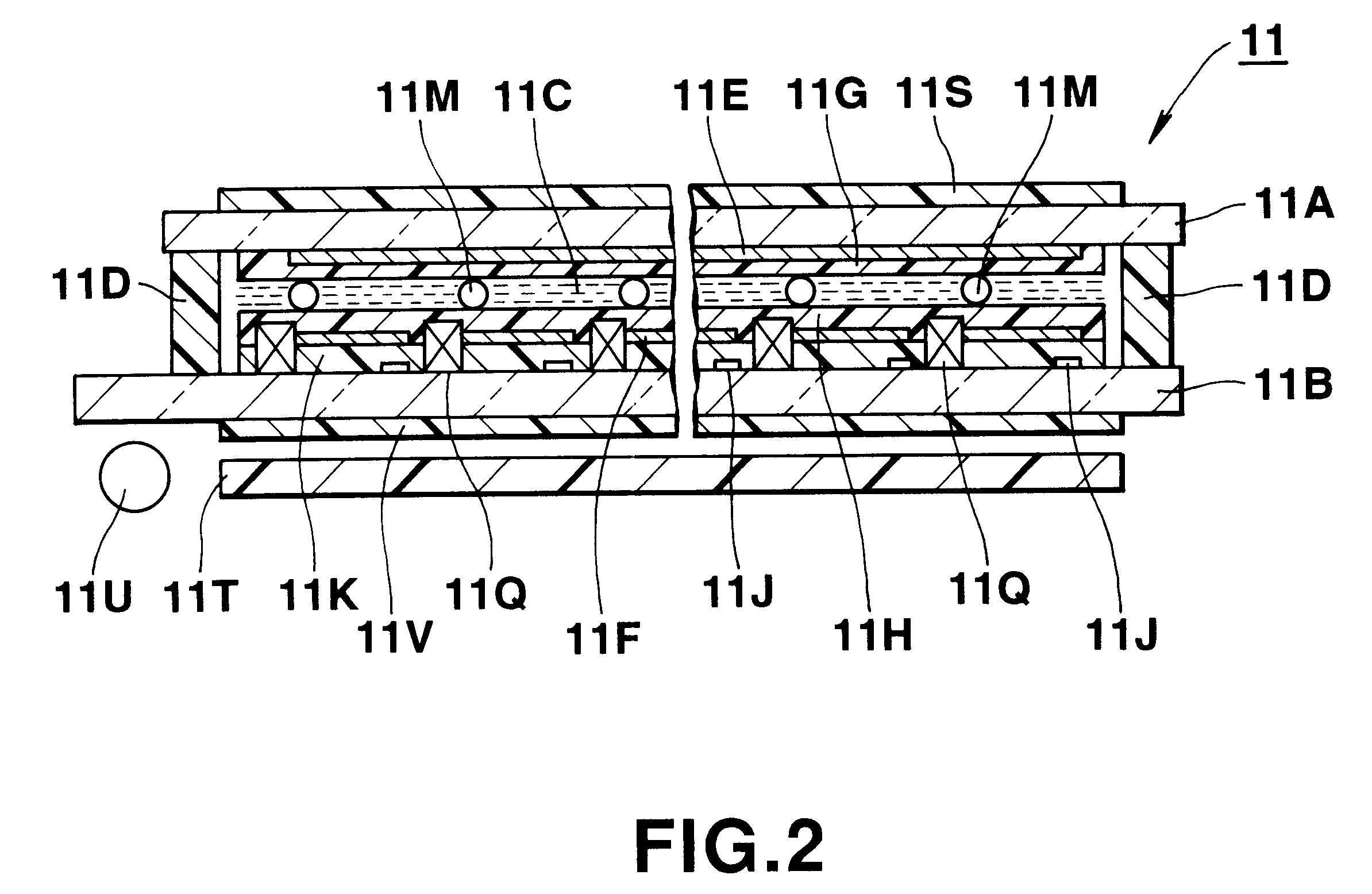
In FIG. 2, t...
second embodiment
This embodiment is an LCD apparatus which capable of displaying data in multi-graduated monochrome.
FIG. 8 shows a schematic representation of the LCD apparatus of the second embodiment. The LCD apparatus shown in FIG. 8 is the same structure with that of the LCD apparatus shown in FIG. 1 except for reset circuits 41 and level modulator circuits 42.
The reset circuit 41 comprises a switch 41a and a reset voltage source 41b. The switch 41a connects to the control circuit 14 and is supplied with a reset signal from the control circuit 14 through the reset signal line 35. The reset voltage source 41b connects to the drain line 18 by way of the switch 41a and the control circuit 14 and provides a reset voltage +Vrs or Vrs to the drain line 18 through the switch 41a in response to the reverse signal Srv supplied from the control circuit 14. That is, the reset circuit 41 supplies the positive reset voltage +Vrs to the drain line 18 during a frame period following a frame period in which the...
third embodiment
This embodiment represents an organic electroluminescent (EL) display apparatus, and schematically represented in FIG. 10. The organic EL display apparatus has the same structure as that of the liquid crystal display apparatus of the second embodiment shown in FIG. 8 except for the addition of an EL display panel 51, a reset voltage source 41c and level modulator circuits 52.
The reset voltage source 41c provides one reset voltage to the drain line 18 through the reset switch 41a because the organic EL display apparatus is always driven with either a positive or negative level of display signals. Further, the control circuit 14 does not invert the polarity of the image data for the same reason.
FIG. 11 shows a structure of one picture element in the organic EL display panel 51. As shown in FIG. 11, the organic EL panel 51 comprises an organic EL element 51a, a data storing capacitor 51b and TFTs 51c and 51d disposed on a transparent substrate 51A. The organic EL element 51a comprises ...
PUM
 Abstract
Description
Claims
Application Information
 - R&D
- Intellectual Property
- Life Sciences
- Materials
- Tech Scout
- Unparalleled Data Quality
- Higher Quality Content
- 60% Fewer Hallucinations
Browse by: Latest US Patents, China's latest patents, Technical Efficacy Thesaurus, Application Domain, Technology Topic, Popular Technical Reports.
© 2025 PatSnap. All rights reserved.Legal|Privacy policy|Modern Slavery Act Transparency Statement|Sitemap|About US| Contact US: help@patsnap.com


