Cross-direction dryer for a machine producing sheet material moving in a machine direction having both gas powered and electric heating portions

a dryer and cross-direction technology, which is applied in the direction of dryers with progressive movements, dryers, stoves or ranges, etc., can solve the problems that the gas infrared drying system cannot control the profil

Inactive Publication Date: 2001-01-02
IMPACT SYST
View PDF21 Cites 32 Cited by
  • Summary
  • Abstract
  • Description
  • Claims
  • Application Information

AI Technical Summary

Benefits of technology

FIG. 6 is a simplified plan view of the an alternative embodiment of a burner portion of the invention.

Problems solved by technology

In general, such gas infrared drying systems have not been capable of profile control (that is of providing differential heat from one zone or slice of the paper being produced to another).

Method used


Image

  • Cross-direction dryer for a machine producing sheet material moving in a machine direction having both gas powered and electric heating portions
  • Cross-direction dryer for a machine producing sheet material moving in a machine direction having both gas powered and electric heating portions
  • Cross-direction dryer for a machine producing sheet material moving in a machine direction having both gas powered and electric heating portions

Examples


Embodiment Construction

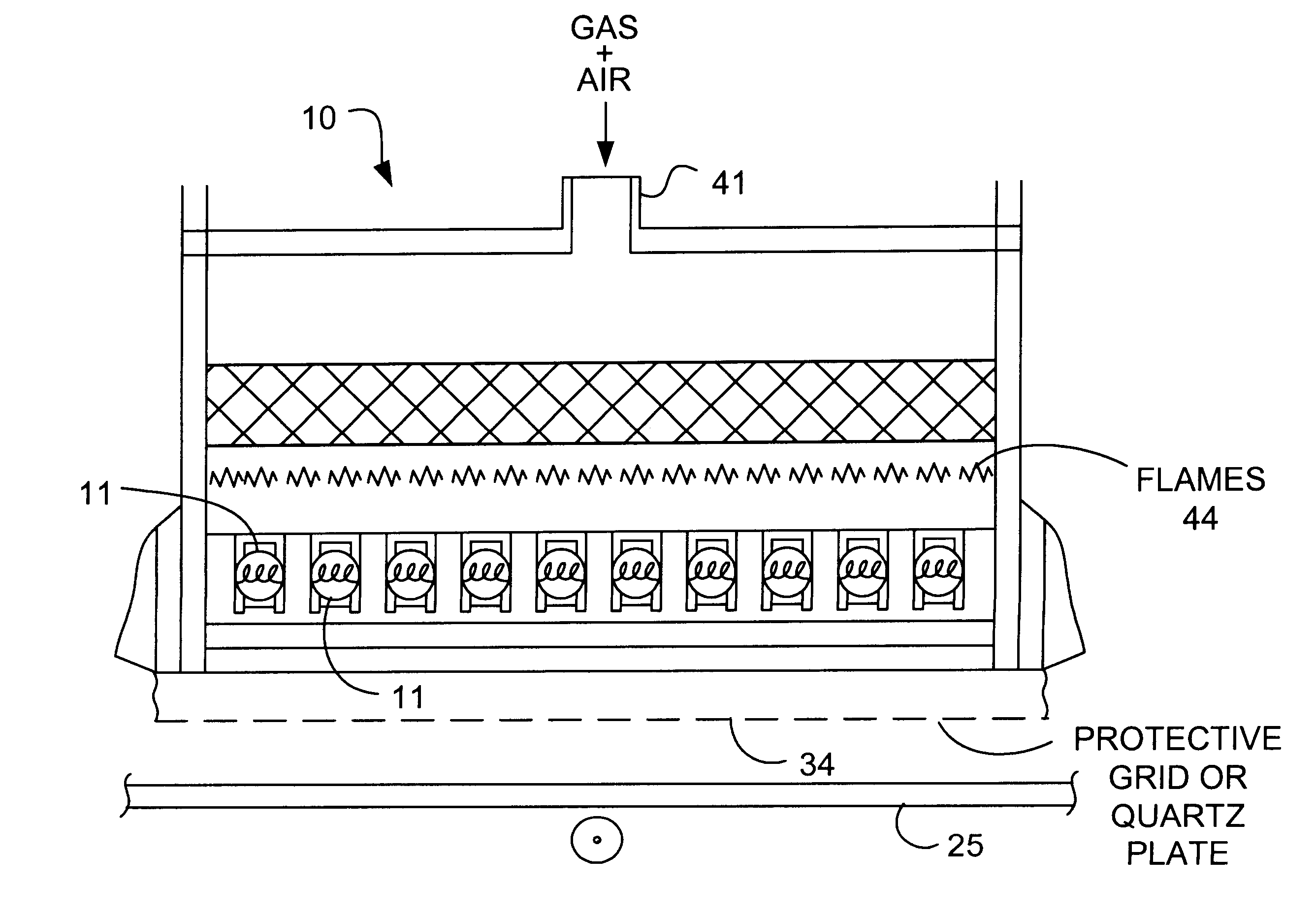
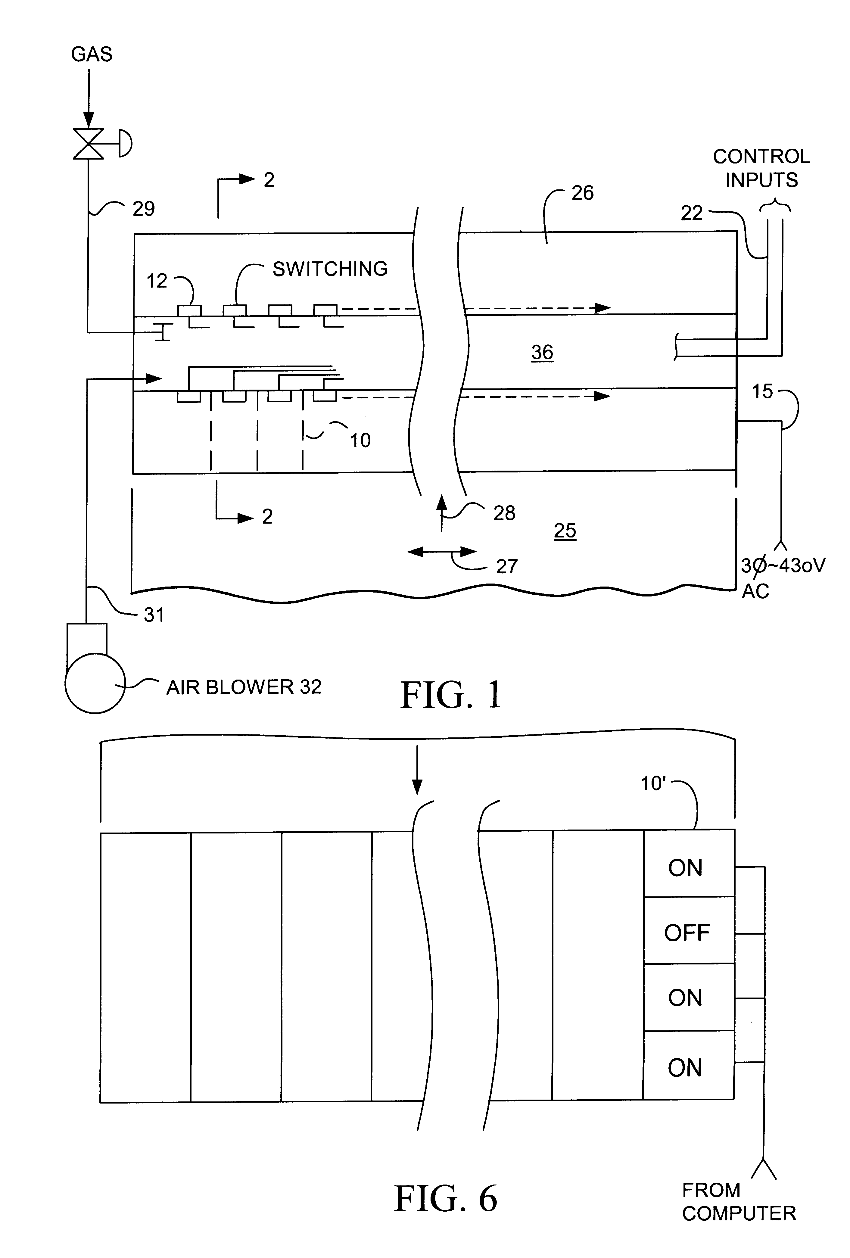
FIG. 1 illustrates a moving web of sheet material 25, such as paper which is being manufactured by a standard paper making machine after being formed through appropriate pressure rollers. It is dried by a plurality of side-by-side combined electric / gas heater units 10 indicated by the dashed lines which are carried by a frame 26. Heater frame 36 spans the width of the sheet 25 in its cross-direction 27. The moving sheet of course has a machine direction 28. Each heater unit 10, may correspond to a zone of for example six inches, also known as a slice, of the paper being manufactured.

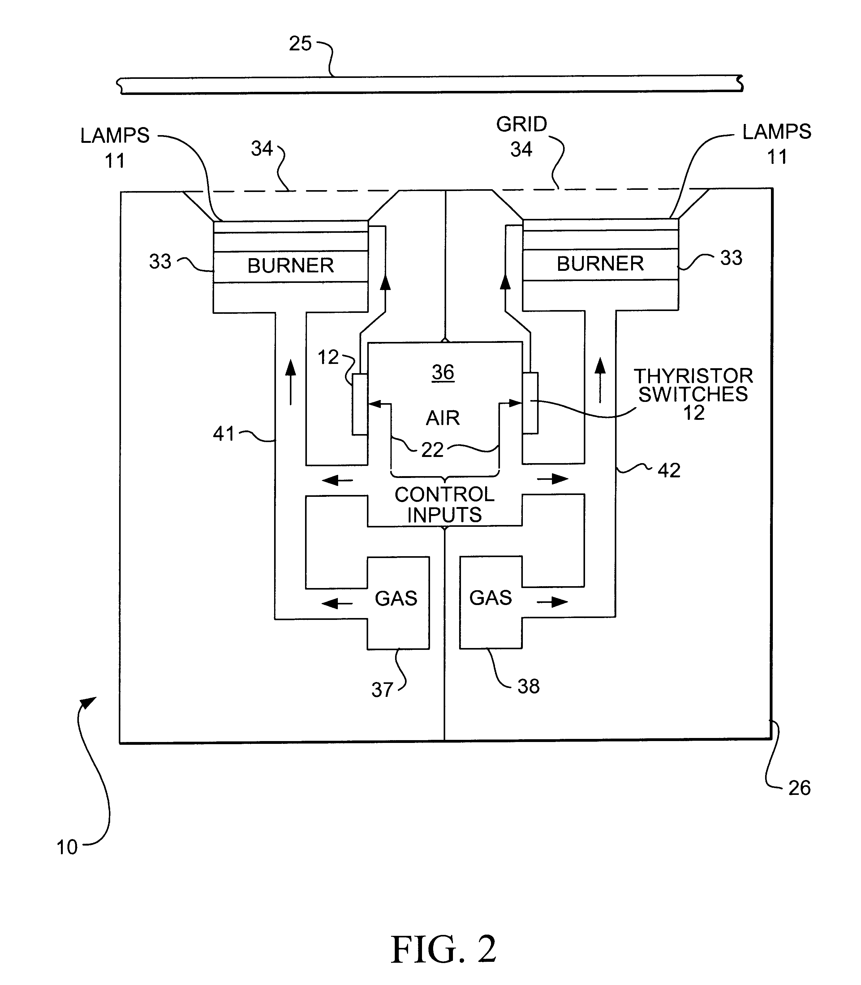
For profile drying purposes the heater unit itself may be divided into smaller, controllable portions. To supply the heater units 10, frame 26 has a gas input 29, a combustion air input 31 including an air blower 32, a 3-phase AC-input 15, which may be for example 430 volts AC, and finally computer control inputs 22. The control inputs 22 each individually control thyristor switching units 12, a pair of ...


PUM

PropertyMeasurementUnit
temperatureaaaaaaaaaa
widthaaaaaaaaaa
impedanceaaaaaaaaaa

Abstract

A cross-direction dryer for typically drying a continuous web of paper or paper to which coating has just been applied provides both for baseline drying and a linear moisture profile by the use of respectively gas and electric heating portions of the heater units. Profile control is normally provided by control of the voltage to electric heating lamps. Such heating lamps are suspended over a large area gas burner to provide a combined increased infrared heat output. Encapsulation of the heating lamps with quartz provides for reradiation of the medium wavelength radiation produced by the gas burner. Thyristor switching for the quartz halogen heat lamps may be located adjacent to each heater unit and cooled by the combustion air for the gas burners.

Description

The present invention is directed to a cross-direction dryer for a machine producing sheet material moving in a machine direction having both gas powered and electric heating portions and more specifically, to a heater for drying moving sheet material such as paper either where uniform moisture content is desired or a recently applied coating to the paper must be dried.Description of Prior ArtRadiant heaters having quartz infrared lamps with tungsten filaments located in the cross-direction of a moving web of paper and which may be individually controlled to provide an even moisture profile are disclosed in U.S. Pat. No. 4,908,956. Here the specific technique of power control of the heat lamps is shown.For drying paper in general for what is termed called baseline drying gas fired infrared burners have been used. In general, such gas infrared drying systems have not been capable of profile control (that is of providing differential heat from one zone or slice of the paper being prod...

Claims


Application Information

Patent Timeline
Patent Type & Authority Patents(United States)
IPC IPC(8): F26B3/00F26B13/00F26B3/30
CPCF26B3/30F26B3/305F26B13/008
Inventor HENRY, LEE L.
Owner IMPACT SYST
Why Eureka
Try Eureka