Iron alloy member and method

a technology of iron alloy and member, applied in the field of wear resistance, high-impact iron alloy member, can solve the problems of increasing operation cost, downtime and maintenance, and affecting and achieve the effect of improving the wear resistance of the member

Inactive Publication Date: 2001-01-09
DALLESPORT FOUNDRY
View PDF9 Cites 41 Cited by
  • Summary
  • Abstract
  • Description
  • Claims
  • Application Information

AI Technical Summary

Benefits of technology

Briefly described, the present invention comprises a wear-resistant, high-impact iron alloy member that includes a front side, positioned to impact rocks to be crushed, which includes at least one raised portion formed of a composite material including a white iron alloy and granular carbide. The provision of carbide material within raised portions of the front impact surface of the alloy member substantially improves wear resistance of the member. Preferably, the front side includes a plurality of raised portions, each formed of a composite material including a white iron alloy and granular carbide. The plurality of raised portions form a series of half column members that receive the brunt of impact forces from the rocks. The front side includes additional raised portions, one of which is an upper rim, another of which is a lower rim, and a third of which is a raised portion between the upper and lower rims, each of which is formed of a composite material including a white iron alloy and granular carbide. This design specifically provides reinforcement at critical points on the front side of the alloy member.

Problems solved by technology

During operation of the rock crusher, the impact surfaces, or wear faces, of the impeller shoes receive tremendous abrasion and wear, which after even a few hours of use require replacement of the shoes.
Consequently, rapidly wearing rock crusher components significantly increases downtime and maintenance, which adds cost to the operation.
However, impeller shoes made from these alloys still require frequent replacement due to significant wear and abrasion.

Method used


Image

  • Iron alloy member and method
  • Iron alloy member and method
  • Iron alloy member and method

Examples


second embodiment

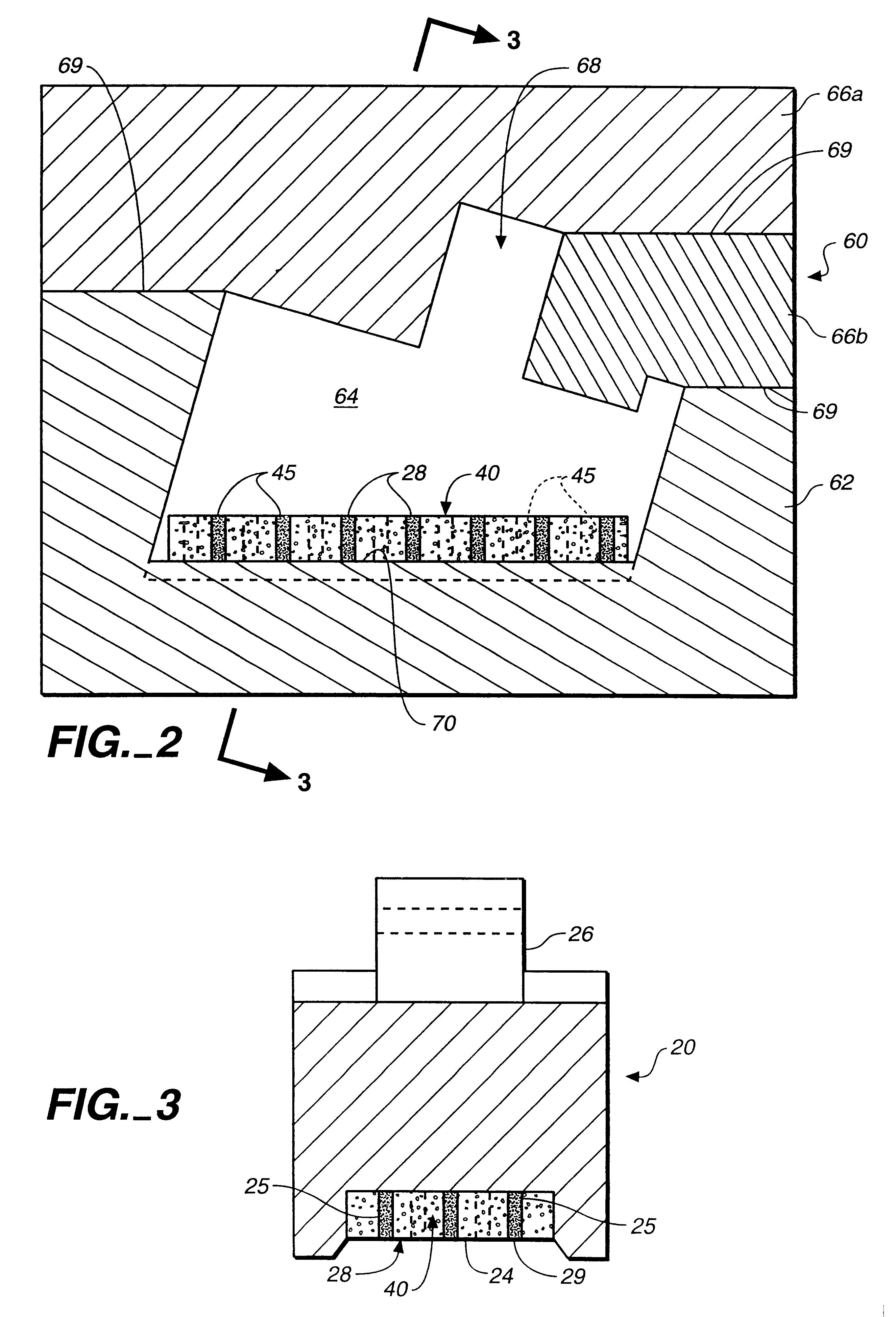
the molding insert in accordance with the present invention is shown in FIGS. 5A and 5B. The molding insert 40 is comprised of a wafer-like, porous ceramic filter material having four side surfaces 42, a top surface 41, and a bottom surface 43. Insert 40 further contains a plurality of bores 45 formed for receipt and containment of carbide granules 29. Preferably, bores 45 extend through insert 40 and are distributed relatively evenly throughout the area of the insert to form a relatively uniform pattern.

Of particular advantage, ceramic member insert 40 is also highly porous and capable of withstanding the high temperature of the molten iron, while allowing the flow of molten iron within the insert to bores 45 holding the carbide granules. Ceramic filters are widely used in the metal casting industry to mechanically remove slag from molten metals so they readily permit flow of the metal through the ceramic wafer without dissolving. Ceramic insert 40 is preferably a porous zirconia c...

examples

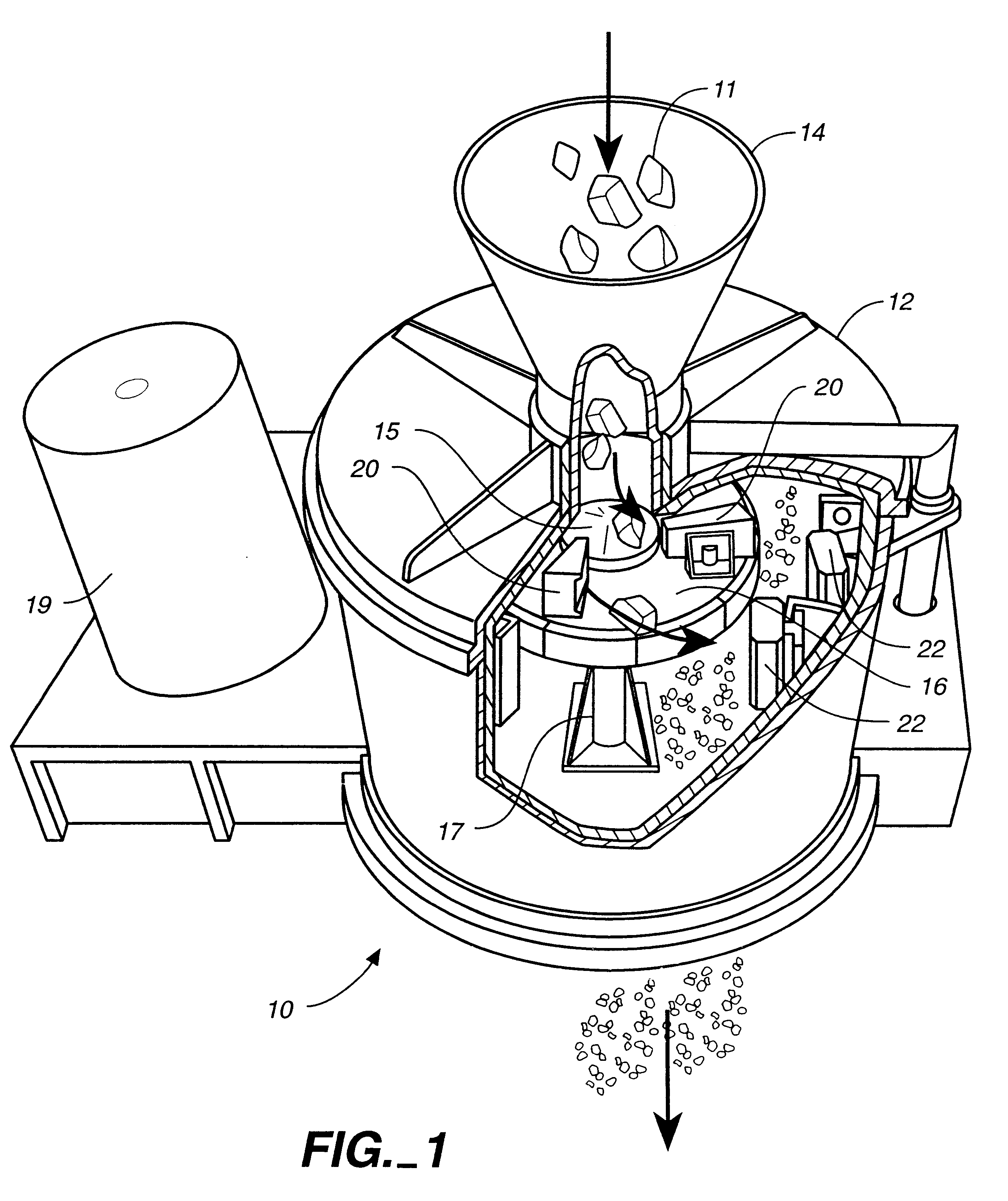
Impellers constructed as shown in FIGS. 2 and 3 have been cast using the method of the present invention with the following constituents:

These impellers have been used in rock crushers and a significant increase (50 to 150%) in the service life of the impellers was achieved.

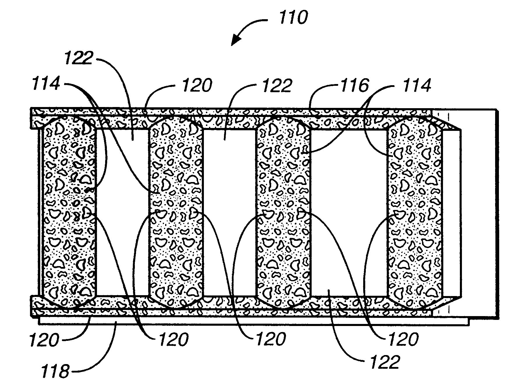
Referring to FIGS. 7 and 8, an alternative embodiment of an impeller shoe 110 is shown that has a carbon reinforced front side 112 that is designed to withstand the impact of rocks. Front side 112 includes a series of four raised portions in the form of half column members or elongated protruding ribs of semi-circular cross section 114 and an upper, raised rim 116 and a lower, raised rim 118. Ribs 114 and rims 116, 118 are formed with a dispersion of carbide granules 120 therein. The method of forming impeller shoe 110 is discussed with reference to FIG. 10.

Raised half columns or transversely extending ribs 114 and rims 116, 118 receive the brunt of rock impact forces and for this reason are reinforced with carbi...


PUM

PropertyMeasurementUnit
temperatureaaaaaaaaaa
weight percentaaaaaaaaaa

Abstract

An impeller shoe (110) having a front side (112) with a series of half column members (114) and raised upper and lower rims (116, 118) that form the impact surface of the impeller shoe. Half columns (114) and raised rims (116, 118) are formed with carbide material (120) formed therein in order to improve wear resistance at these critical surfaces.

Description

The present invention relates generally to iron alloy members with improved wear resistance and a method of making the same, and more specifically to white iron alloy members of the type employed in centrifugal impact rock crushers.Wear and abrasion resistant, high impact, iron alloy members are employed in a variety of applications, in particular, in rock crushing machines for crushing rocks and ore. A common machine used for crushing rocks is a centrifugal rock crusher, such as disclosed in U.S. Pat. No. 5,533,685.Centrifugal rock crushing apparatus typically contain cast iron impact members called impeller shoes, which throw or propel rocks against stationary members called anvils to effect crushing of the rock. Both the impeller shoes and the anvils are subjected to repeated, high force impact loading, which of course is necessary to break apart the rocks. During operation of the rock crusher, the impact surfaces, or wear faces, of the impeller shoes receive tremendous abrasion ...

Claims


Application Information

Patent Timeline
Patent Type & Authority Patents(United States)
IPC IPC(8): B02C13/28B02C13/18B02C13/00B22D19/06C21D5/00C21D5/04
CPCB02C13/1814B02C13/2804B22D19/06C21D5/04Y10T428/12979Y10T428/12951Y10T428/12486Y10T428/12576
Inventor SMITH, JERRY I.STOUT, ANTHONY E.
Owner DALLESPORT FOUNDRY
Why Eureka
Try Eureka