Wood I-beam conditioned reinforcement panel

a technology of conditioned reinforcement and conditioned beams, which is applied in the direction of girders, joists, wood layered products, etc., can solve the problems of increasing the cost of steel web wood i-beams, and requiring the use of oversized flanges of lower quality wood, etc., to achieve the effect of increasing the ductility ratio, increasing the resistance to these failure modes, and increasing the strength of greater

Inactive Publication Date: 2001-01-16
OREGON CASCADES WEST COUNCIL OF GOVERNMENTS
View PDF30 Cites 69 Cited by
  • Summary
  • Abstract
  • Description
  • Claims
  • Application Information

AI Technical Summary

Benefits of technology

Failure in conventional steel web wood I-beams typically occurs in a flange, in cleavage, compression, or tension, in the vicinity of the pins coupling the flanges and metal web. Lateral buckling of the compression flange also occurs. The reinforcements provide the wood flanges of this invention with enhanced resistance to these failure modes, as well as to failure in the vicinity of finger joints where portions of the wood flanges are joined end-to-end and to failure in the vicinity of local defects in the flanges (e.g., knots in compression-side flange). As a result, metal web wood I-beams of this invention can be manufactured with flanges of lower grades of wood and have comparable or greater strength than conventional steel web wood I-beams. Also, the reinforcements function to increase the ductility ratio (i.e., the ultimate load over the yield point load) of

Problems solved by technology

Conventional manufacturing practices provide steel web wood I-beams that are of generally high quality and have generally high design limits that include having adequate stiffness to meet application deflection criteria.
The limited availability of affordable high

Method used


Image

  • Wood I-beam conditioned reinforcement panel
  • Wood I-beam conditioned reinforcement panel
  • Wood I-beam conditioned reinforcement panel

Examples


Embodiment Construction

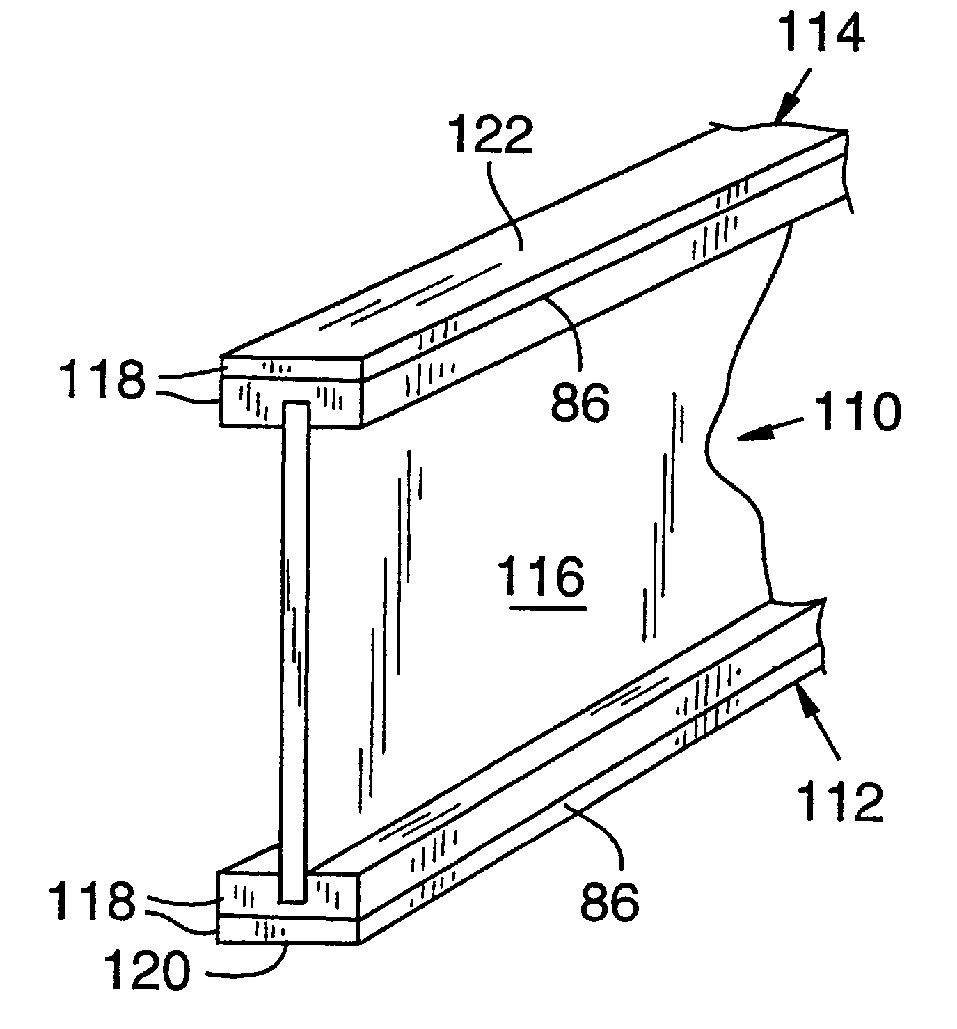
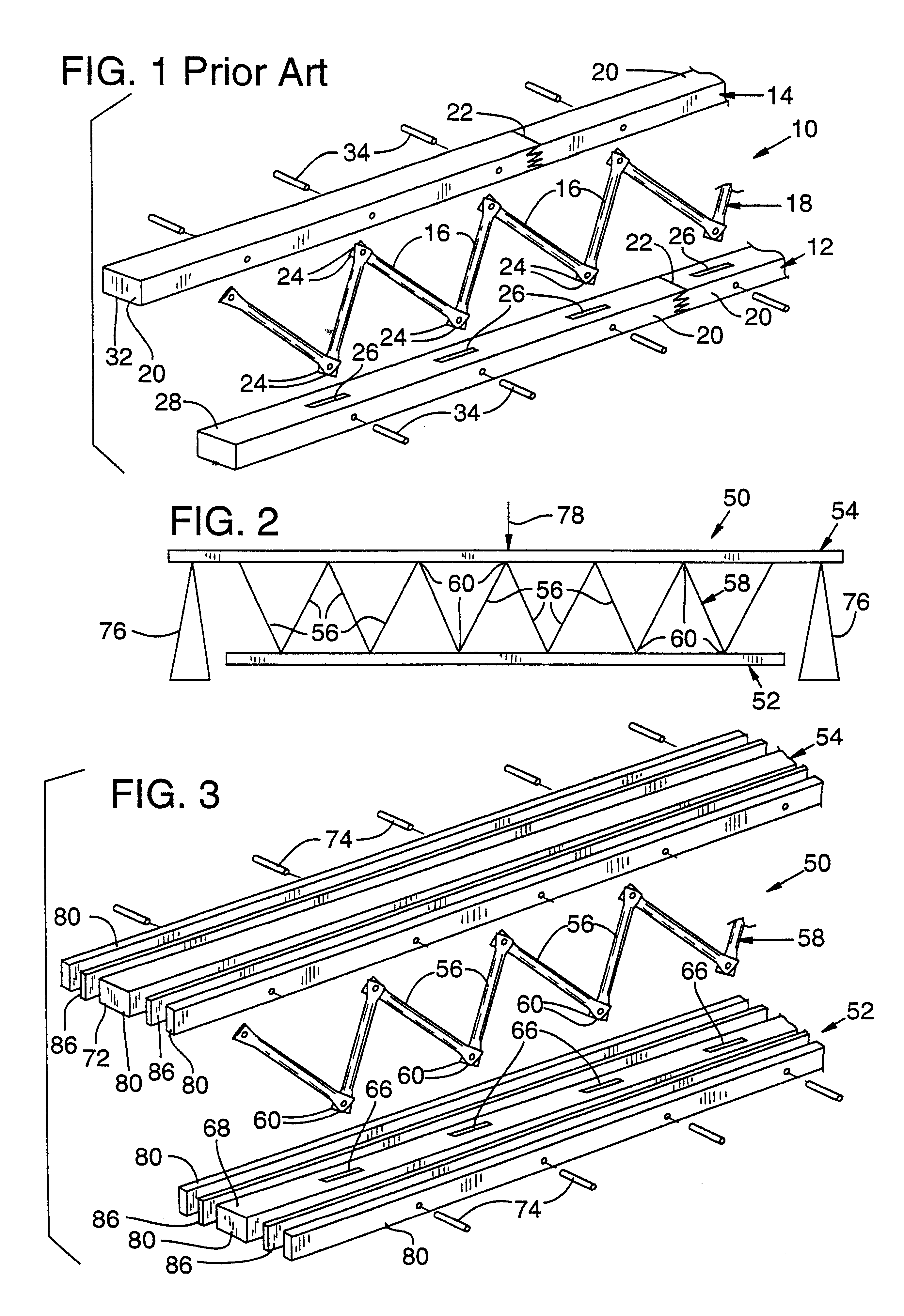
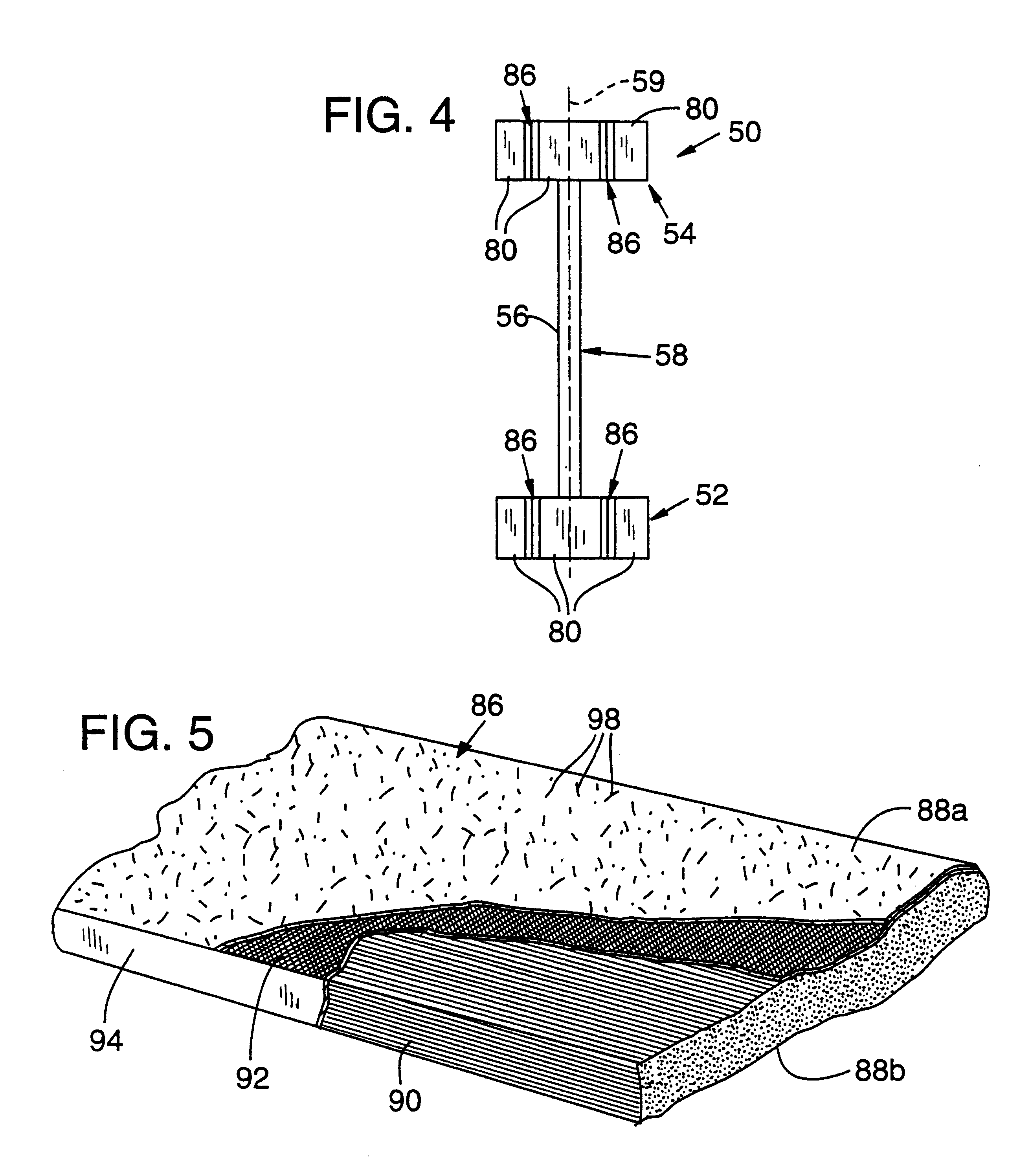
FIGS. 3 and 4 show a metal web wood I-beam 50 that includes an opposed pair of elongated wood flanges 52 and 54 that have positioned between them multiple straight metal (e.g., steel) tubes 56 arranged as a substantially continuous tubular metal web 58 that preferably forms a zig zag pattern and defines a plane 59 (FIG. 4) that extends through flanges 52 and 54. Metal tubes 56 have ends 60 that are flattened parallel to plane 59 of metal web 58 to fit within either slots 66 in top surface 68 of flange 52 or similar slots (not shown) in bottom surface 72 of flange 54. Metal pins 74 pass through the sides of flanges 52 and 54 and flattened ends 6C of tubes 56 to secure them to flanges 52 and 54.

A typical structural use of metal web wood I-beam 50 is to extend as a beam or joist over and bear a load along an otherwise open region. As a simplified, exemplary representation of such use, metal web wood I-beam 50 is shown in FIG. 2 with its ends supported by a pair of blocks 76 and bearing...


PUM

PropertyMeasurementUnit
Thicknessaaaaaaaaaa
Thicknessaaaaaaaaaa
Lengthaaaaaaaaaa

Abstract

The present invention includes wood I-beams with fiber reinforcement. In a preferred embodiment, a wood I-beam includes an opposed pair of elongated wood flanges and a substantially continuous web positioned between them. In one embodiment, the web includes multiple metal tubes that extend between the wood flanges and form a zig zag pattern. The ends of the metal tubes are flattened parallel to the plane of the metal web so the ends can fit within either slots in the top surface of the bottom wood flange or slots in the bottom surface of the top wood flange. Metal pins pass through the sides of the wood flanges and the flattened ends of the metal tubes to secure the tubular metal web to the flanges. In other embodiments the web includes oriented strand board (OSB) or plywood. Reinforcements are adhered to the wood flanges so that the metal pins also pass through the reinforcements. The reinforcements preferably include multiple fiber strands held within a resin matrix.

Description

TECHNICAL FIELDThe present invention relates to wood structural members and, in particular, to improved wood I-beams.BACKGROUND OF THE INVENTIONBeams, trusses, joists, and columns are the typical structural members that support the weight or loads of structures, including buildings and bridges. Structural members may be manufactured from a variety of materials, including steel, concrete, and wood, according to the structure design, environment, and cost.Wood structural members are now typically manufactured from multiple wood segments that are bonded together, such as in glue-laminated members, laminated veneer, parallel strand wood and I-beams. These manufactured wood structural members have replaced sawn lumber or timbers because the former have higher design limits resulting from better inspection and manufacturing controls. Wood is a desirable material for use in many structural members because of its various characteristics, including strength for a given weight, appearance, cy...

Claims


Application Information

Patent Timeline
IPC IPC(8): B32B21/08B32B21/10B29C70/04B29C70/02B29C70/00B32B5/12B32B21/00B29C70/08B32B5/22B29C70/52B32B5/26B29C70/54D04H5/04D04H5/00D04H3/02E04C3/29D04H5/08D04H1/00E04C3/17E04C3/18E04C3/292E04C3/12E04C3/14
CPCB29C70/025B29C70/08B29C70/083B29C70/52B29C70/525B29C70/54B32B5/12B32B5/26B32B21/08B32B21/10D04H1/005D04H3/02D04H5/04D04H5/08E04C3/122E04C3/14E04C3/17E04C3/18E04C3/185E04C3/291E04C3/292B29K2105/101
Inventor TINGLEY, DANIEL A.
Owner OREGON CASCADES WEST COUNCIL OF GOVERNMENTS
Why Eureka
Try Eureka