Linear motion bearing assembly with load compensation

a technology of load compensation and bearings, applied in the direction of bearings, bearings, bearing shafts, etc., can solve the problems of premature bearing failure, low bearing performance, and low bearing performance, and achieve the effect of improving rolling performance and bearing life and reducing the cost of labor and equipmen

Inactive Publication Date: 2001-01-16
THOMSON IND INC
View PDF10 Cites 30 Cited by
  • Summary
  • Abstract
  • Description
  • Claims
  • Application Information

AI Technical Summary

Benefits of technology

In accordance with the present invention, a linear motion bearing assembly is provided which is easily and efficiently manufactured to increase the useful life of the assembly. The assembly can control load deflection characteristics with pressure transducer structure configured to engage deflectable structure of the assembly.

Problems solved by technology

Typically, a constant low coefficient of friction of a predetermined magnitude is required in those applications where a load can cause the linear motion bearing assembly to skid which impairs rolling performance.
However, excessive load compensation can cause uneven or overloading of the rolling elements which may result in pitting, spalling or cracking at the bearing surface of the rolling elements, causing premature bearing failure.
This method results in relatively high costs in terms of labor and equipment.
This method is difficult to implement since the screws must be adjusted in an even manner to uniformly alter the resulting pressure on the rolling elements.
Additionally, the adjusting screws are subject to loosening due to machine-generated shock and vibration.
Permanent strain can occur preventing any further adjustment.
The life of the bearing will be compromised.
These conventional methods of load compensation are time consuming, labor intensive and require a high degree of precision.
The result is inefficiency in achieving economical production of anti-friction bearings having predetermined load bearing characteristics.

Method used


Image

  • Linear motion bearing assembly with load compensation
  • Linear motion bearing assembly with load compensation
  • Linear motion bearing assembly with load compensation

Examples


Embodiment Construction

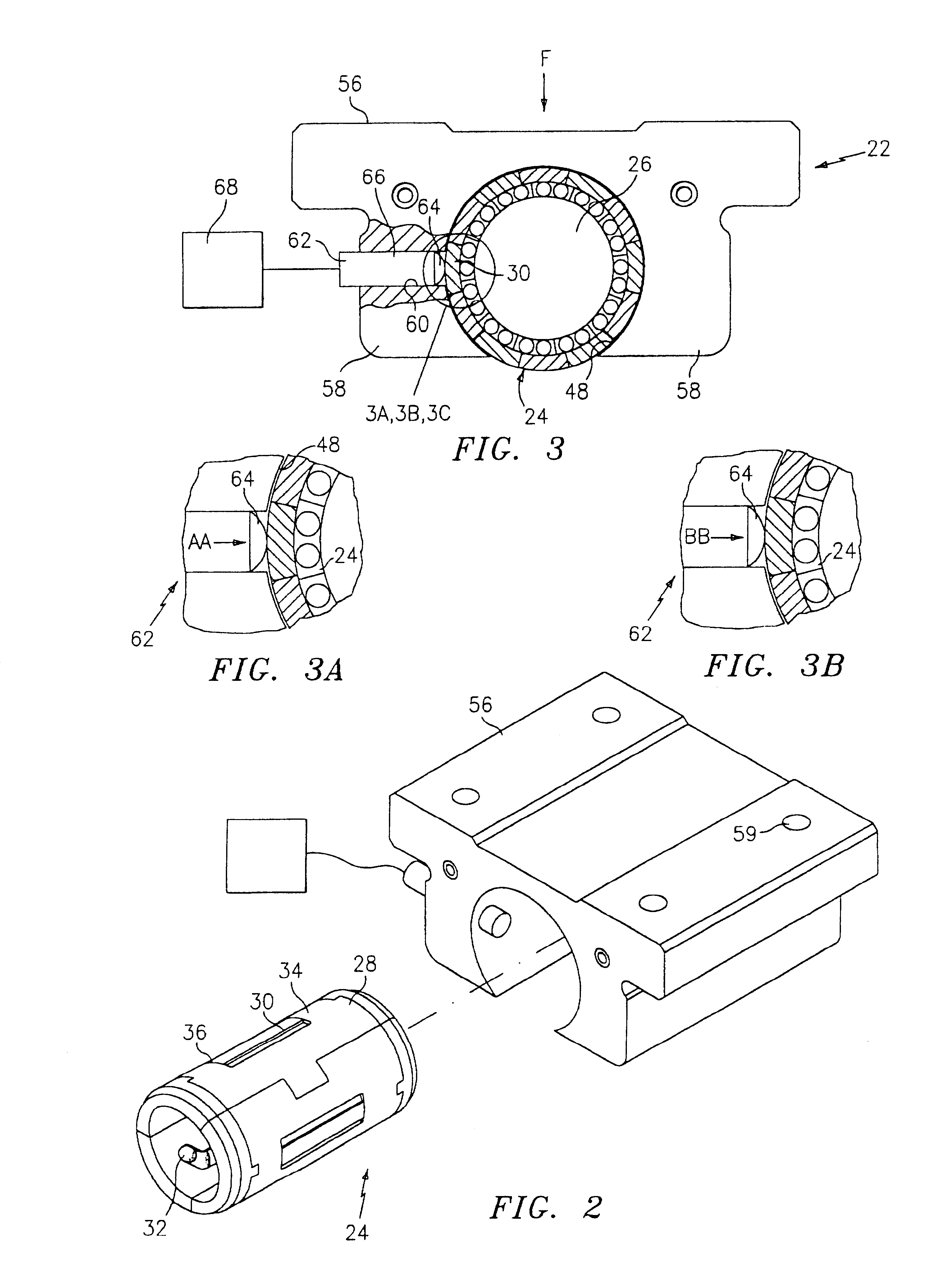
Referring now to the drawings in detail, wherein like reference numerals identify similar structural elements of the subject invention, there is illustrated linear motion bearing assemblies including deflectable structure configured to deform under a predetermined force to affect load bearing characteristics of the assembly.

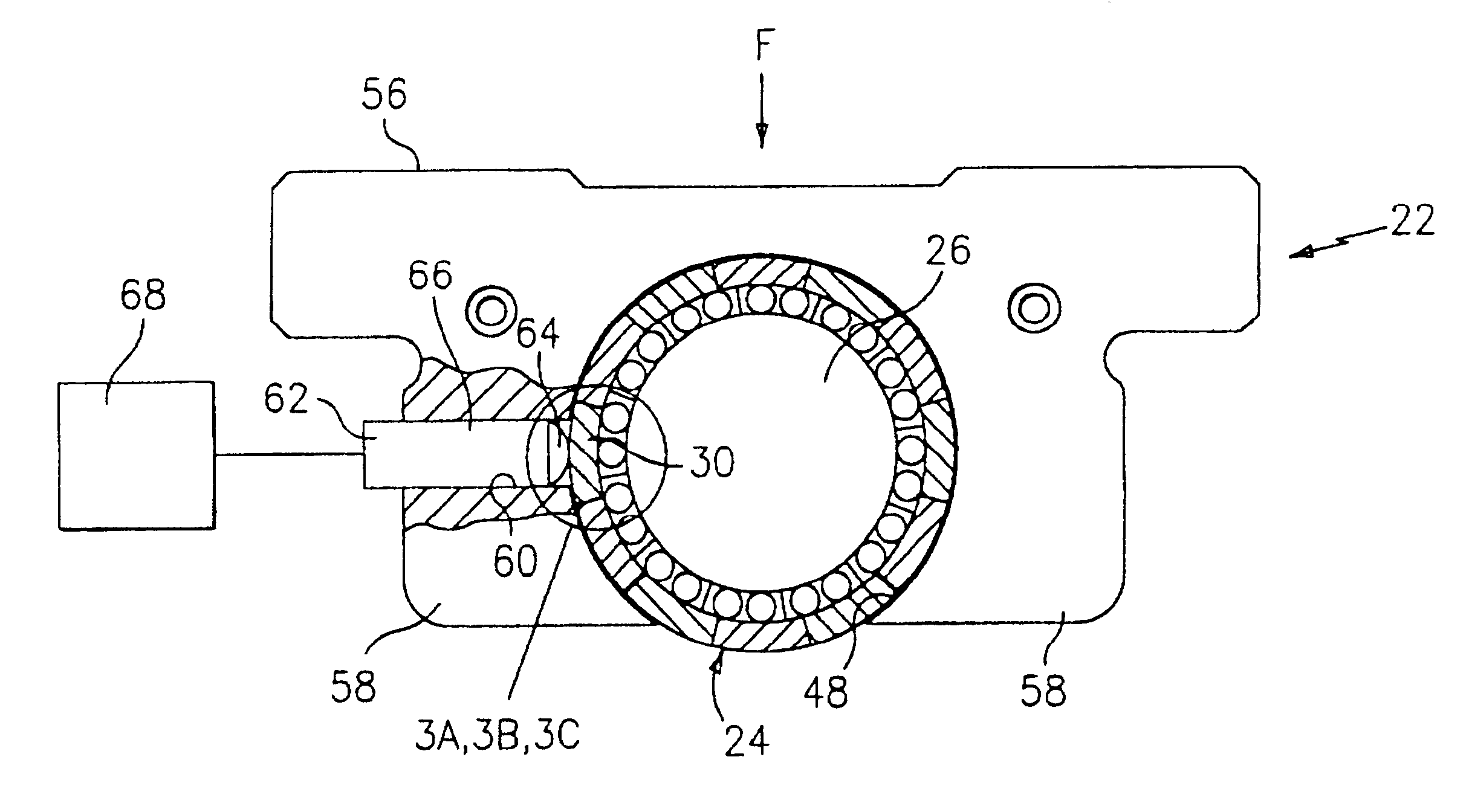
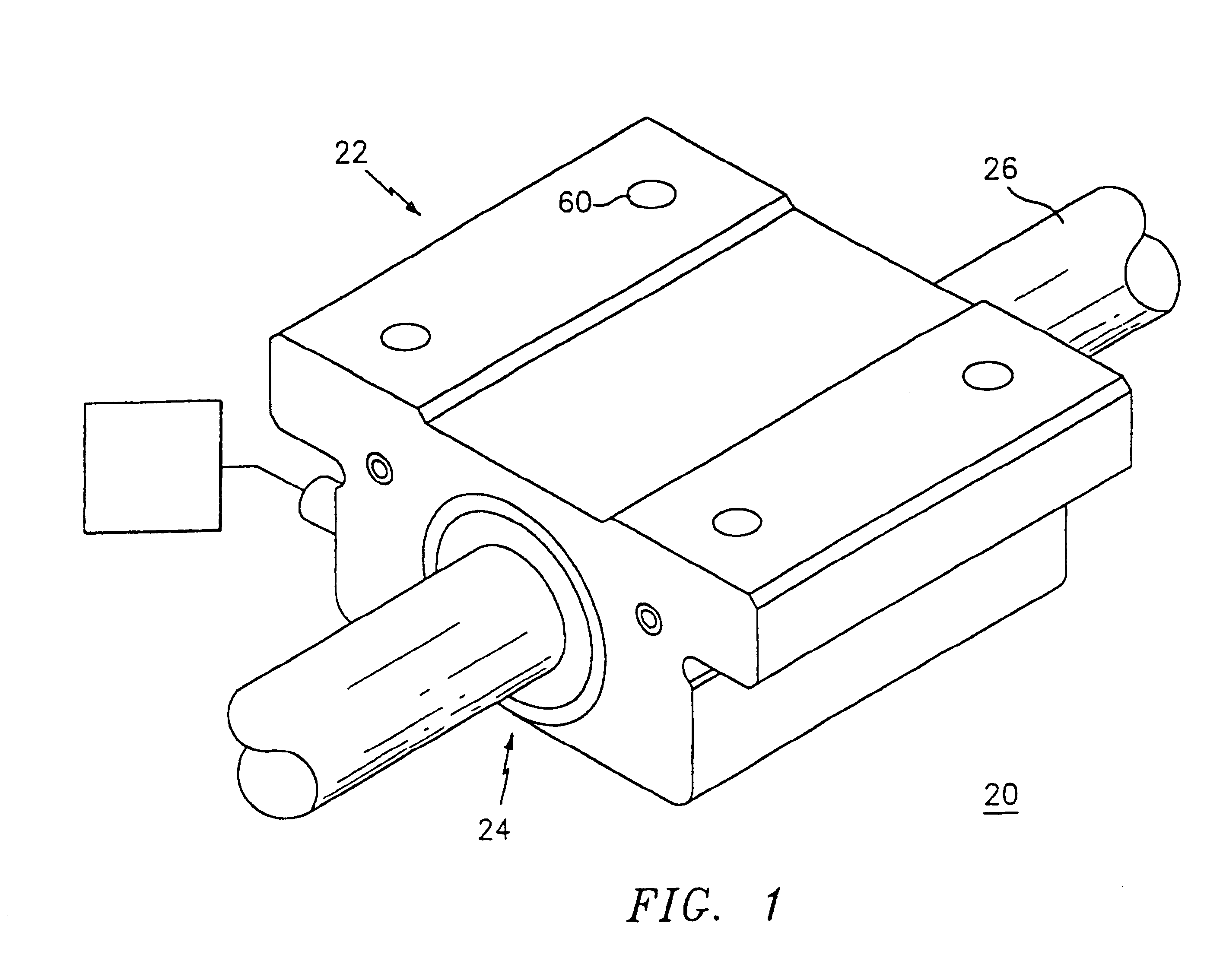
Referring initially to FIG. 1, a linear motion bearing assembly, designated generally by the numeral 20, in accordance with the present invention, is shown. Linear motion bearing assembly 20 includes an open type bearing carriage 22 configured and dimensioned for receipt of a bearing assembly 24 for movement along a rail 26. The deflectable structure includes the bearing assembly, as will be discussed hereinbelow.

Pressure transducer structure is disposed adjacent to and configured for engaging the deflectable structure to apply a predetermined force on the deflectable structure in response to external stimuli. The external stimuli may include externally applied l...


PUM


Abstract

A linear motion bearing assembly is provided including a carriage, a rail, and a bearing assembly. The linear motion bearing assembly includes deflectable structure formed in at least one of the carriage, rail and bearing assembly. The deflectable structure is configured to deflect under a predetermined force to affect load bearing characteristics of the linear motion bearing assembly. Pressure transducer structure is disposed adjacent to and configured for engaging the deflectable structure to apply the predetermined force to affect load bearing characteristics. The deflectable structure may include portions of the rail defining a cavity. The pressure transducer structure is disposed within the cavity. In another embodiment, the carriage includes a sidewall depending therefrom whereby the deflectable structure includes the sidewall. In yet another embodiment, the bearing assembly includes a ball retainer having a load bearing plate aperture. The deflectable structure includes a load bearing plate positioned within the aperture. The pressure transducer structure may include piezoelectric structure.

Description

1. Field of the InventionThe present invention relates to anti-friction linear motion bearing assemblies and, more particularly, to linear motion bearing assemblies configured to affect load bearing characteristics of the assembly.2. Description of the Related ArtThe present invention is directed to improvements in linear motion bearing assemblies. In particular, the improvements relate to linear motion bearing assemblies of the type whereby a bearing carriage or pillowblock houses a linear bearing assembly for linear movement along a support member, such as, for example, an elongated shaft, rail or spline. The inside bore of the carriage or pillowblock houses the linear bearing.These linear bearing assemblies are used extensively in a wide variety of machines, machine tools, transfer systems and other equipment where machine elements move with respect to one another. These assemblies, typically, include a bearing carriage mounted for movement along a modified Y-beam, I-beam or T-be...

Claims


Application Information

Patent Timeline
Patent Type & Authority Patents(United States)
IPC IPC(8): F16C29/06F16C29/04F16C29/00F16C29/12
CPCF16C29/00F16C29/04F16C29/0604F16C29/0645F16C29/0647F16C29/069F16C29/12
Inventor PAUWELS, WILLIAM A.LYON, GREGORY S.
Owner THOMSON IND INC
Why Eureka
Try Eureka