
Integrated circuit testing device with dual purpose analog and digital channels

Inactive Publication Date: 2001-01-16
CREDENCE SYSTEMS
View PDF3 Cites 38 Cited by
  • Summary
  • Abstract
  • Description
  • Claims
  • Application Information

AI Technical Summary

Problems solved by technology

There is an inherent waste in such fixed allocation system for vector fields when the range of test activities and timing carried out by a channel during a test is relatively smaller than the range of activities and times that can be defined by a fixed length vector with reserved fields.
A general purpose tester with both analog and digital channels will typically not be able to use all its channel memory resources during any particular test.
Thus depending on the type of DUT being tested, much of the channel memory and other resources of the tester remain idle.
If a tester could more flexibly allocate its resources, particularly its memory resources, it could perform longer and more complicated tests.
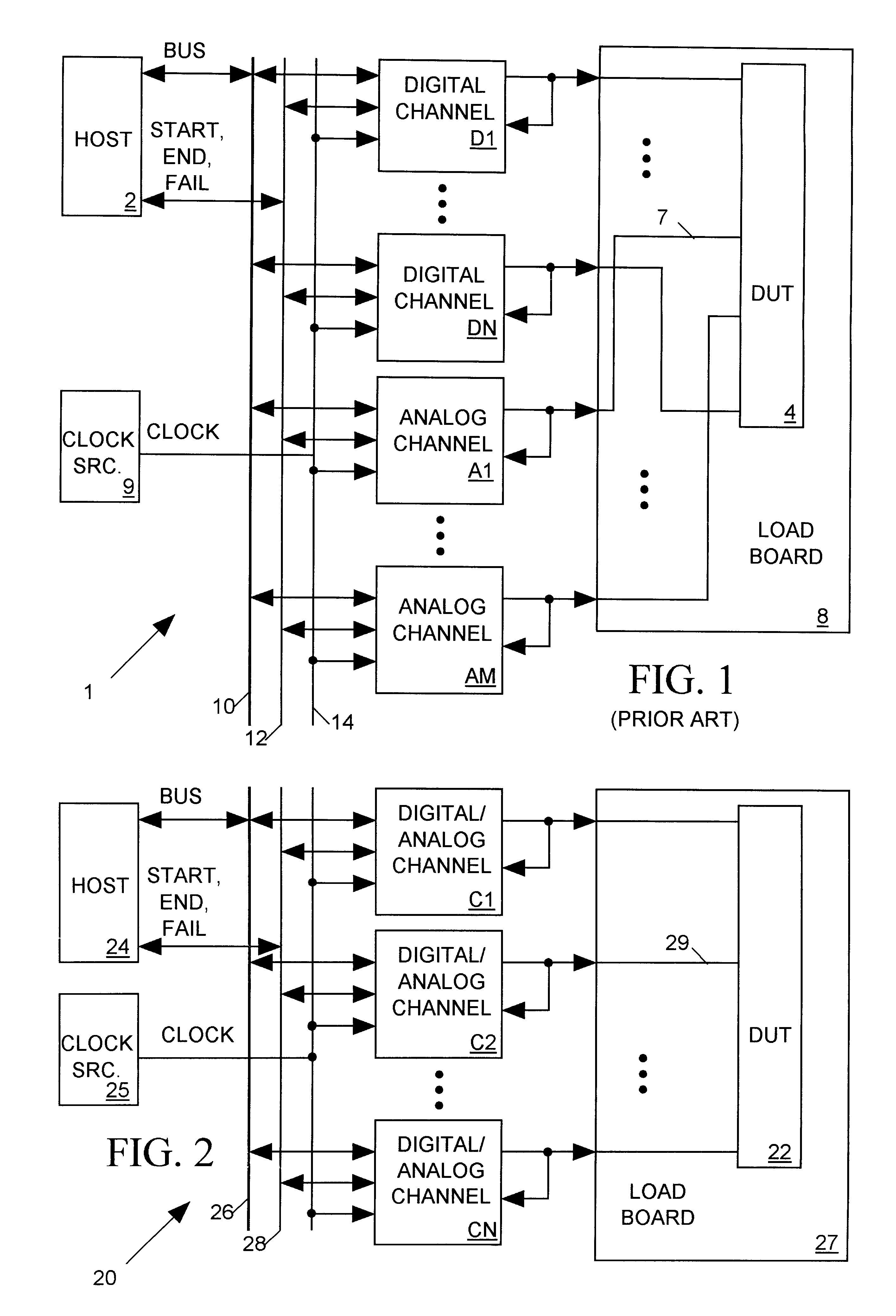
Since the tester architecture of FIG. 1 includes both the analog and digital channels, and since each channel requires a certain amount of space in the tester, it is difficult to position them as closely to the DUT as in a tester employing only digital channels.
Since a general purpose analog / digital tester must be able to test DUTs having a wide variety of analog and digital pin arrangements, it is not possible to know how best to configure the tester's channels.
We do not know how to best allocate resources between analog and digital channels and we do not know how to best position analog and digital channels so as to minimize signal path distances.
A test channel configuration that may be optimal for one DUT pin arrangement will not be optimal for a DUT having a different pin arrangement.
Since host computer 2 may have to send a large amount of data to the channels over bus 10 in order to reprogram them, such reprogramming effort between tests often requires substantially more time than the tests themselves.
This reprogramming time substantially limits the throughput of a tester.

Method used


Image

  • Integrated circuit testing device with dual purpose analog and digital channels
  • Integrated circuit testing device with dual purpose analog and digital channels
  • Integrated circuit testing device with dual purpose analog and digital channels

Examples


Embodiment Construction

)

Tester Architecture

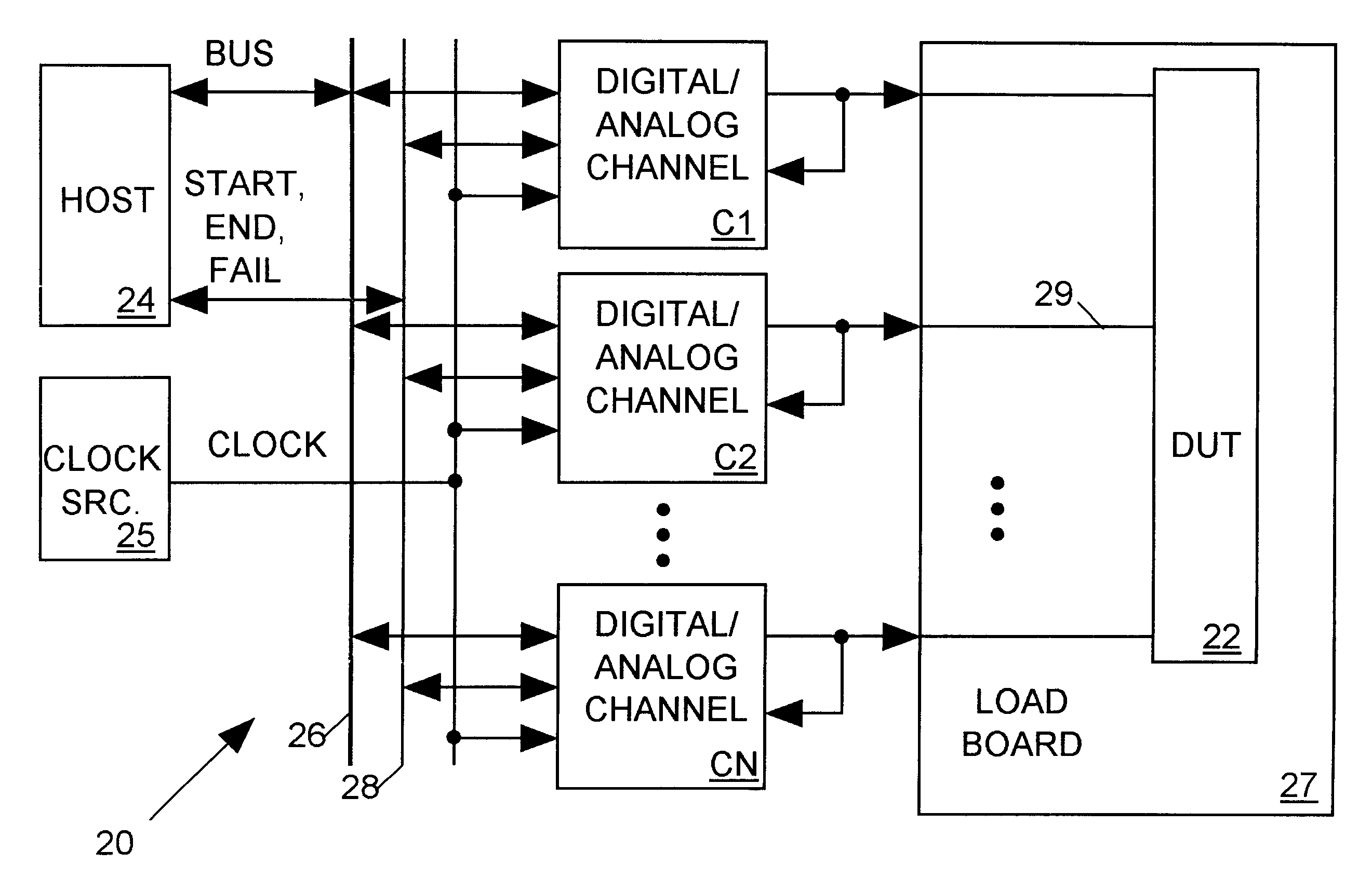
FIG. 2 illustrates in block diagram form an integrated circuit (IC) tester 20 in accordance with the present invention for testing an IC device under test (DUT) 22. DUT 22 may be a device such as an analog-to-digital converter communicating through both analog and digital signals. Tester 20 includes a set of N dual-purpose channels C1-CN, each for carrying out a sequence of test activities at a separate input / output (I / O) terminal of DUT 22. A load board 27 on which DUT 22 may be mounted during testing includes a set of traces 29 for connecting each channel C1-CN to a corresponding I / O terminal of DUT 22.

A test is organized into successive test cycles marked by an edge of each pulse of a CLOCK signal supplied to each channel C1-CN from a central clock source 25. During each test cycle, each channel C1-CN may supply either an analog or a digital test signal input to a DUT 22 input terminal or may digitize and process a DUT analog or digital output signal appearing...


PUM


Abstract

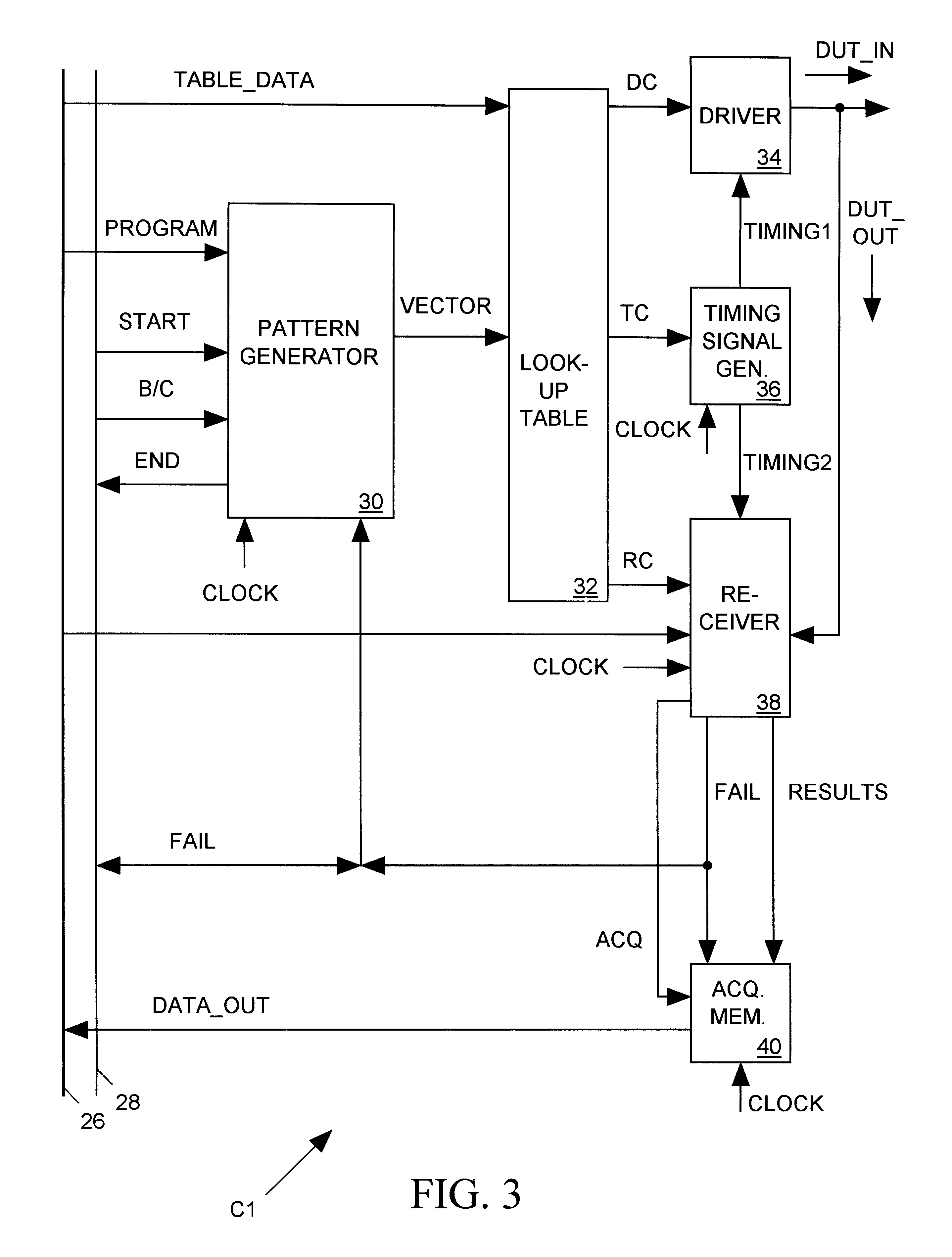
An integrated circuit (IC) tester includes a set of dual-purpose digital / analog channels. Each tester channel includes a driver capable of supplying either a digital or analog test signal input to an IC terminal and a receiver for digitizing and processing either an analog or digital IC output signal appearing at the DUT terminal to produce results data representing the behavior of that IC output signal during a test. A test is organized into a succession of test cycles, and before each test cycle a pattern generator within each channel produces data for controlling the behavior of the driver and receiver during the test cycle. The control data controls whether the driver is to produce an analog or a digital test signal, controls a magnitude or logic level to which the test signal is to be driven during the test cycle, and controls a time during the test cycle of any test signal state or magnitude changes. The control data also indicates how and when the receiver digitizes and processes an IC output signal during the test cycle.

Description

1. Field of the InventionThe present invention relates in general to integrated circuit (IC) testers and in particular to a tester having both analog and digital testing capability in each of its channels.2. Description of Related ArtWhen an integrated circuit (IC) such as an analog-to-digital converter (ADC) or a digital-to-analog converter (DAC) has both analog and digital input / output signals it has to be tested with an integrated circuit tester having both analog and digital channels. For example to test an ADC, the tester must supply an analog input signal to the ADC and monitor the sequence of digital output signals it produces to determine whether the ADC is properly digitizing its analog input signal. Conversely to test a DAC, the tester must supply a sequence of digital data values as input to the DAC and then monitor the DAC's analog output signal to determine whether it exhibits the behavior defined by the input data sequence.FIG. 1 illustrates a typical general purpose I...

Claims


Application Information

Patent Timeline
IPC IPC(8): G01R31/316G01R31/3183G01R31/28G01R31/319G06F11/00G06F11/22H04B1/74
CPCG01R31/31924
Inventor DINTEMAN, BRYAN J.
Owner CREDENCE SYSTEMS
Learn More