
Method and apparatus for hierarchical global routing descend

a global routing and hierarchical technology, applied in the field of microelectronic integrated circuits, can solve the problems of inability to handle the layout of the entire circuit, physical design is not practical without the aid of computers,

Inactive Publication Date: 2001-01-16
BELL SEMICON LLC
View PDF17 Cites 157 Cited by
  • Summary
  • Abstract
  • Description
  • Claims
  • Application Information

AI Technical Summary

Problems solved by technology

Due to the large number of components and the exacting details required by the fabrication process, physical design is not practical without the aid of computers.
Layout of the entire circuit cannot be handled due to the limitation of memory space as well as the computation power available.

Method used


Image

  • Method and apparatus for hierarchical global routing descend
  • Method and apparatus for hierarchical global routing descend
  • Method and apparatus for hierarchical global routing descend

Examples


Embodiment Construction

I. METHOD AND APPARATUS FOR PARALLEL SIMULTANEOUS GLOBAL AND DETAILED ROUTING

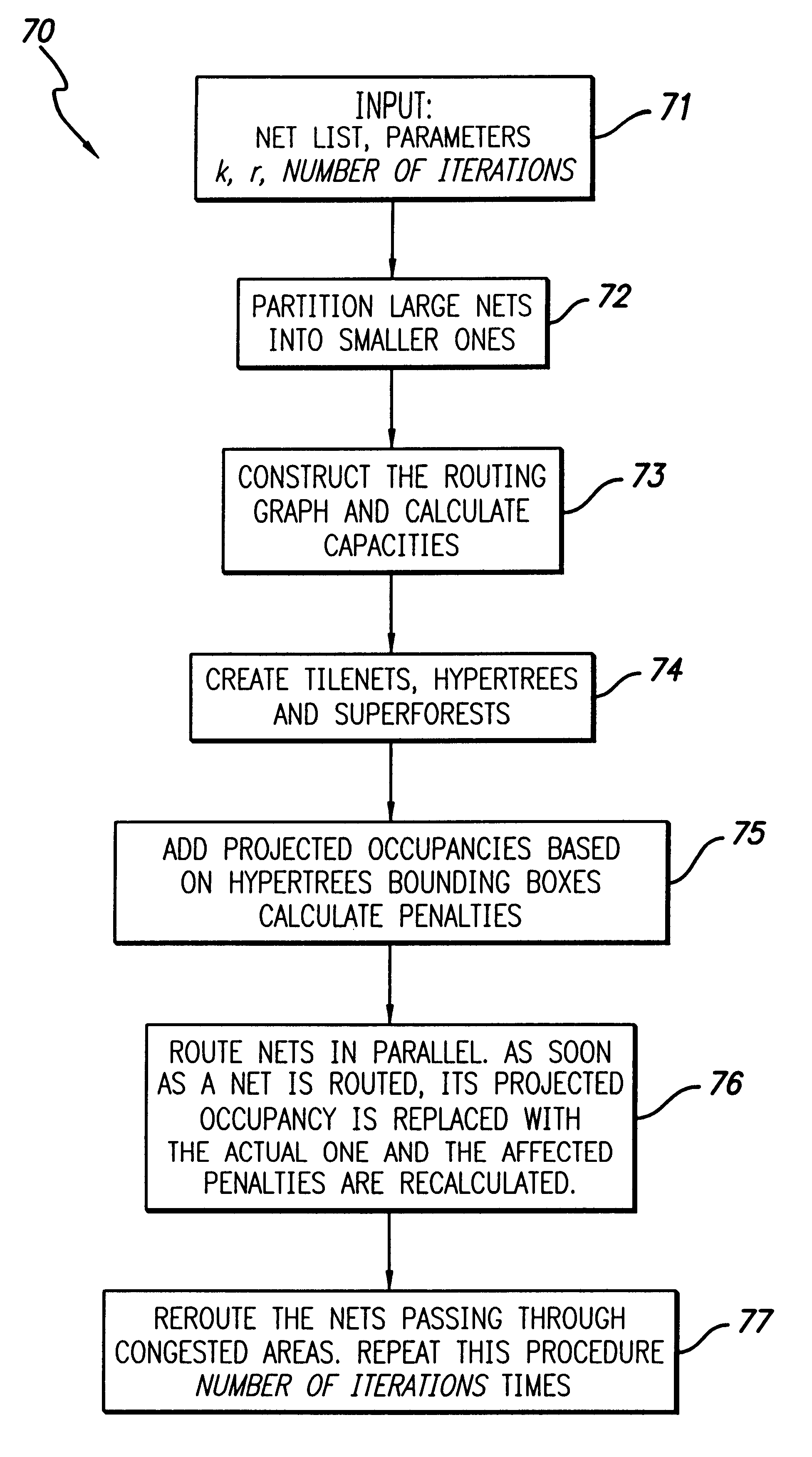
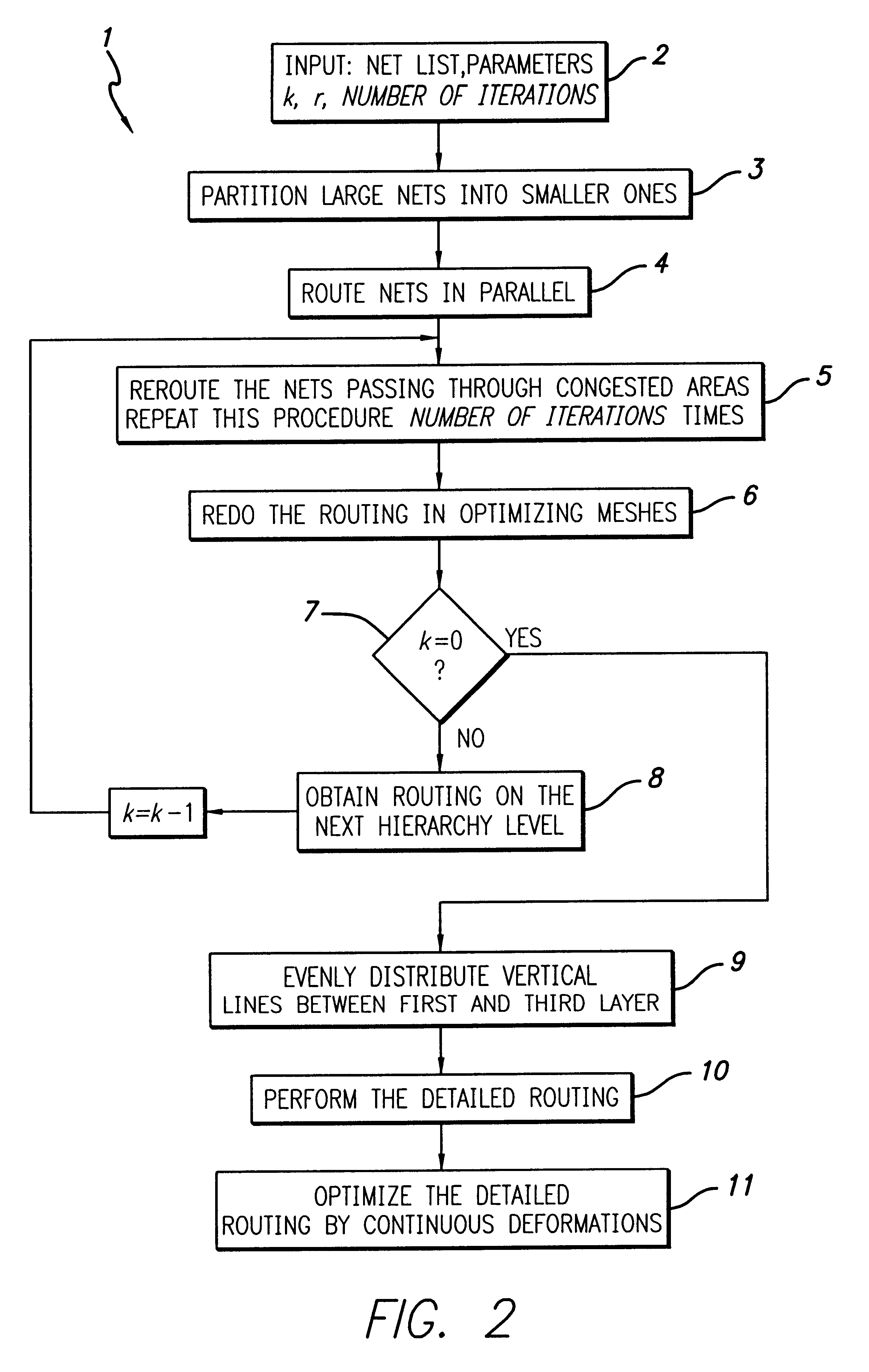
Described in this Section I ("Method and Apparatus for Parallel Simultaneous Global and Detailed Routing") is a system for routing an integrated circuit in parallel. The system takes into account congestion and routes nets so as to avoid congested areas. The system also minimizes process defects by spreading wires as evenly as is possible. This routing system utilizes several steps as are shown in FIG. 2. FIG. 2 is a flow chart 1 that shows the basic steps of the routing system.

As an initializing step 2, certain information must be input into the system, including the netlist and certain specified parameters. The parameters include k, r, number of iterations, each of which is discussed more fully below. Additional parameters may also be input at this point of the operations. Such additional parameters include the parameter D (described more fully below in Section II), the parameter K (described more fully b...


PUM


Abstract

Net routing is optimized in an integrated circuit device by dividing an integrated circuit design with a first group of substantially parallel lines in a first direction and with a group of substantially parallel lines in a second direction, with the second direction being substantially perpendicular to the first direction. A first routing graph is formed with vertices corresponding to locations where lines in the first direction and lines in the second direction cross, and nets are globally routed as a function of the first routing graph. The integrated circuit design is further subdivided with a second group of substantially parallel lines in the first direction, and a second routing graph is formed with vertices corresponding to locations where lines in the first and second groups of substantially parallel lines in the first direction cross lines in the group of substantially parallel lines in the second direction. For a net globally routed using the first routing graph, a first local net is formed in a first fragment of the second routing graph, and the first local net is rerouted within the first fragment by computing edge penalty values for edges in the first fragment and rerouting the first local net as a function of the edge penalty values.

Description

BACKGROUND OF THE INVENTION1. Field of the InventionThe present invention generally relates to the art of microelectronic integrated circuits. In particular, the present invention relates to the art of processing high fanout nets for purposes of routing integrated circuit chips.2. Description of Related ArtAn integrated circuit chip (hereafter referred to as an "IC" or a "chip") comprises cells and connections between the cells formed on a surface of a semiconductor substrate. The IC may include a large number of cells and require complex connections between the cells.A cell is a group of one or more circuit elements such as transistors, capacitors, and other basic circuit elements grouped to perform a function. Each of the cells of an IC may have one or more pins, each of which, in turn, may be connected to one or more other pins of the IC by wires. The wires connecting the pins of the IC are also formed on the surface of the chip.A net is a set of two or more pins which must be co...

Claims


Application Information

Patent Timeline
IPC IPC(8): G06F17/50
CPCG06F17/5077G06F30/394
Inventor SCEPANOVIC, RANKOANDREEV, ALEXANDER E.GASANOV, ELYAR E.RASPOPOVIC, PEDJA
Owner BELL SEMICON LLC
Features
  • Generate Ideas
  • Intellectual Property
  • Life Sciences
  • Materials
  • Tech Scout
  • Unparalleled Data Quality
  • Higher Quality Content
  • 60% Fewer Hallucinations
Learn More