
Biopsy method and device

a biopsy and device technology, applied in the field of biopsy methods, can solve the problems of inability to justify small practices, high cost and time consumption of such equipment,

Inactive Publication Date: 2001-01-23
MURRAY PACHAL FAMILY TRUST TRUSTEES MURRAY PACHAL JAN PACHAL ROBERT PARKINSON
View PDF4 Cites 17 Cited by
  • Summary
  • Abstract
  • Description
  • Claims
  • Application Information

AI Technical Summary

Benefits of technology

guiding the biopsy needle to the calculated site by minimising the shadows so that the needle remains substantially parallel to the electromagnetic radiation beam.

Problems solved by technology

A critical issue in the conducting of core biopsies is the accurate location of suspect tissue (hereinafter referred to as a lesion), and thereafter the accurate guiding of the biopsy needle to the lesion.
The use of such equipment is expensive and time consuming, and cannot be justified in small practices.

Method used


Image

  • Biopsy method and device
  • Biopsy method and device
  • Biopsy method and device

Examples


Embodiment Construction

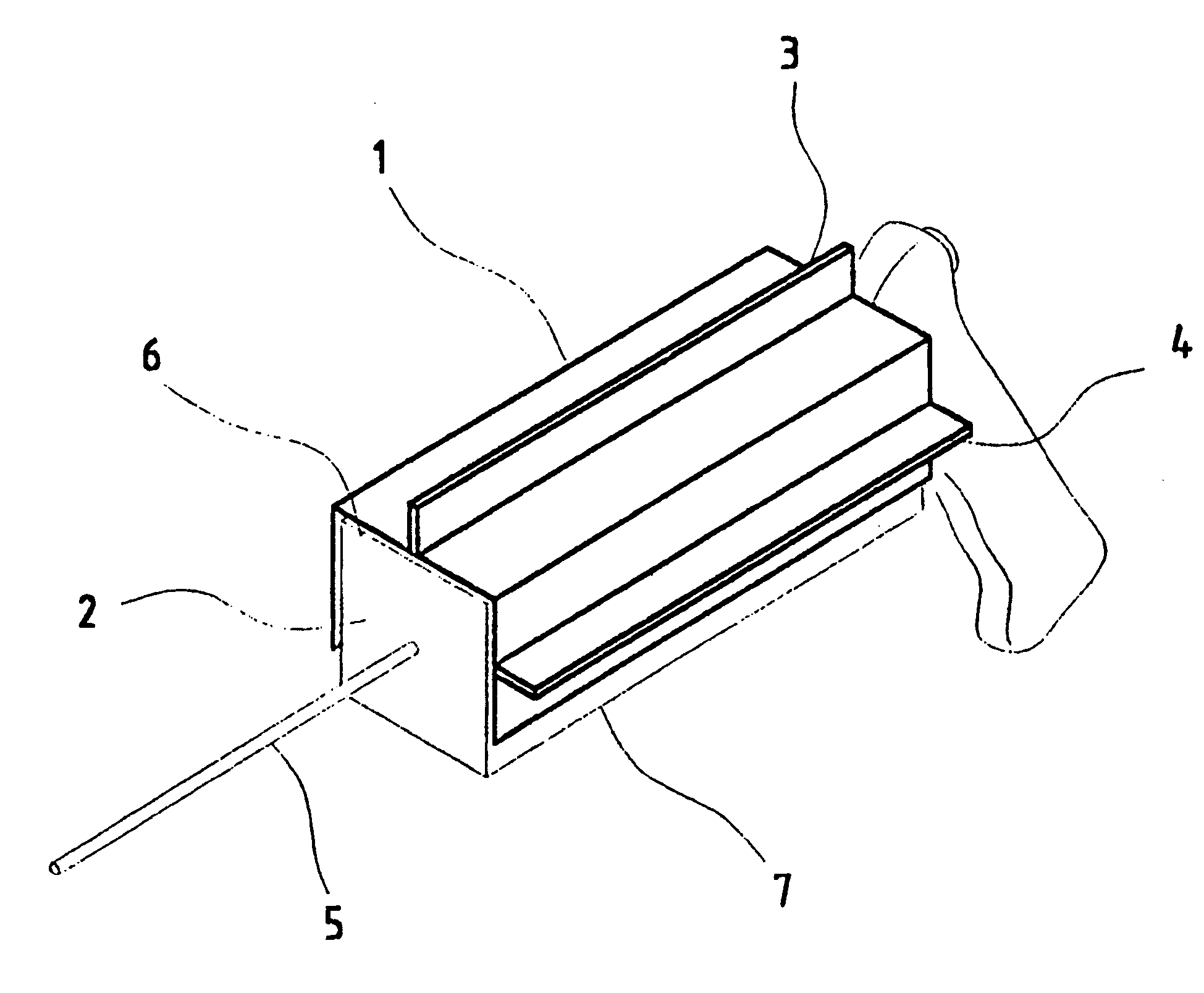
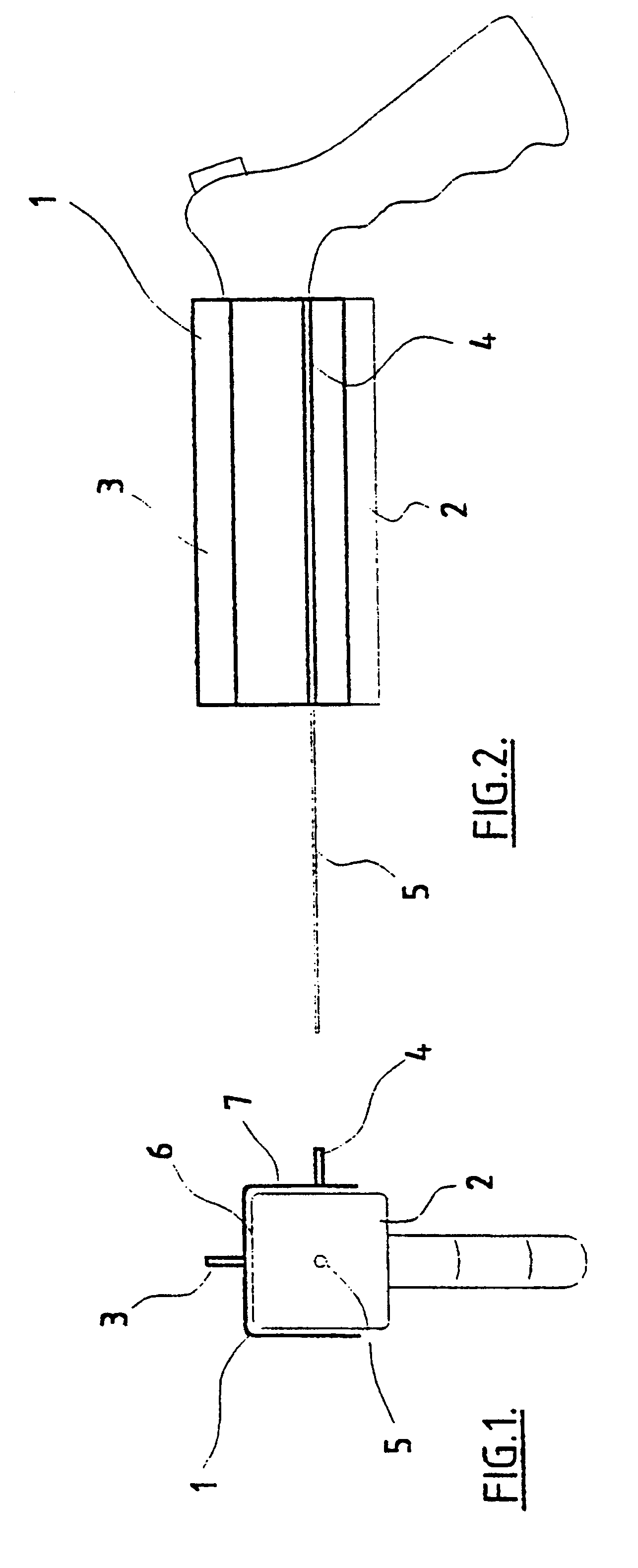
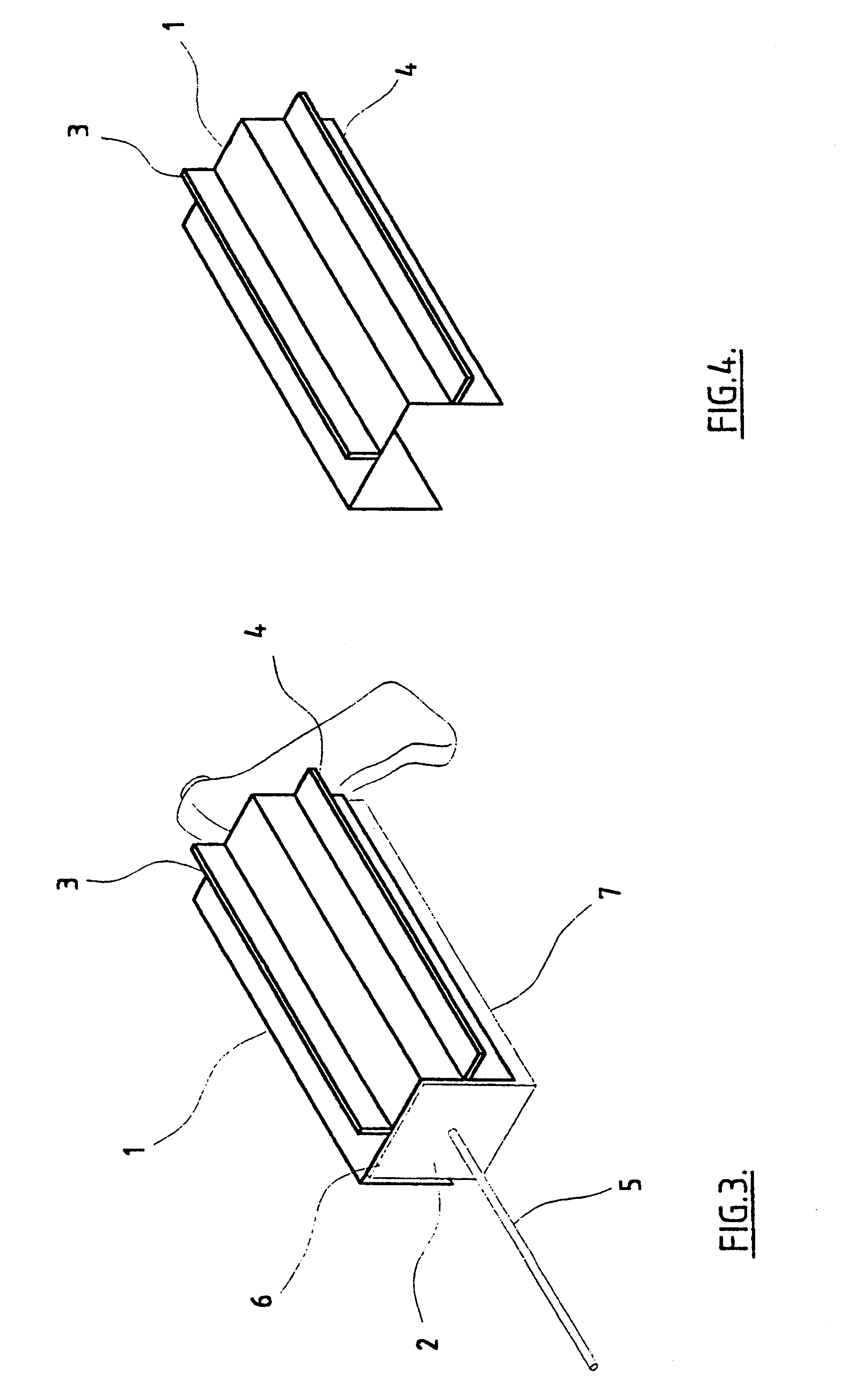
The apparatus of the present invention involves the use of winged guides for a biopsy gun, as shown in FIGS. 1-4. A winged guide 1 may be in the form of a clip-on device adapted to securely engage with a biopsy gun 2. The winged guide 1 has a first wing 3 in one plane and a second wing 4 in a plane at 90.degree. to the plane of the first wing 2. Each wing extends substantially the length of the biopsy gun 2. The winged guide 1 is constructed such that when positioned on a biopsy gun the first 3 and second 4 wings are at 90.degree. to one another and both are in line with the position of the needle 5 in the biopsy gun 2, i.e. if the needle is positioned centrally at the end of the biopsy gun then the first wing 3 is positioned half way along a first side 6 of the biopsy gun 2, whilst the second wing 4 is positioned half way along an adjacent side 7 of the biopsy gun 2.

In the example shown in FIG. 4 the winged guide 1 is an elongate structure having three sides, and adapted to securel...


PUM


Abstract

This invention relates to a method of performing accurate biopsies, particularly core breast biopsies, and a device for facilitating the accuracy of the taking of biopsies. The device involves the provision of guiding members or wing-type projections on at least two sides of the barrel of a biopsy gun. Each guiding member is parallel to the axis of a biopsy needle attached to the gun and there are at least two guiding members projecting from the barrel of the gun substantially perpendicular to one another. Each guiding member is preferably in line with the needle, so that in use the biopsy needle is in the plane of each guiding member. The device may be in the form of a biopsy gun with the guiding members integrally formed or affixed, or it may be in the form of an attachment for attaching to a conventional biopsy gun. The method of the invention involves a means of guiding a biopsy needle to a calculated site of a target lesion; identifying a location on the skin surface directly between the calculated site and a source of electromagnetic radiation, including a light source; positioning a biopsy needle tip at that location; monitoring shadows on the skin surface created by guiding members on a biopsy gun to which the biopsy needle is attached, each guiding member projecting from a side of the biopsy gun, in a parallel axis to the needle attached or held by the gun, and at least two of the guiding members substantially perpendicular to one another; and guiding the biopsy needle to the calculated site by minimizing the shadows so that the needle remains substantially parallel to the electromagnetic radiation beam.

Description

This invention relates to a method and apparatus for facilitating biopsies, and particularly core breast biopsies.A critical issue in the conducting of core biopsies is the accurate location of suspect tissue (hereinafter referred to as a lesion), and thereafter the accurate guiding of the biopsy needle to the lesion. Sophisticated methods and apparatus have been developed for core biopsies in connection with mammography.Stereotactic breast biopsy involves the taking of a first radiographic image of a lesion in a breast, moving the breast or x-ray tube a known distance and then taking a second radiographic image of the lesion in the breast, so that the x, y and z coordinates of the lesion site in the breast may be calculated.Once the location of the lesion has been confirmed, most biopsy needles and their associated biopsy guns are computer-controlled to drive the biopsy needle to the calculated position in the breast. The use of such equipment is expensive and time consuming, and c...

Claims


Application Information

Patent Timeline
IPC IPC(8): A61B17/34A61B10/00A61B10/02
CPCA61B10/0275A61B17/3403
Inventor PACHAL, MURRAY
Owner MURRAY PACHAL FAMILY TRUST TRUSTEES MURRAY PACHAL JAN PACHAL ROBERT PARKINSON
Learn More